- Automobile training equipment series
- Electrical and electronic teaching equipment
- Elevator training series
- Fitter training equipment
- Fluid mechanics experimental equipment
- Hydraulic and pneumatic test bench
- Mechanical teaching equipment
- Robotic automation and mechatronics series
- Welding training equipment

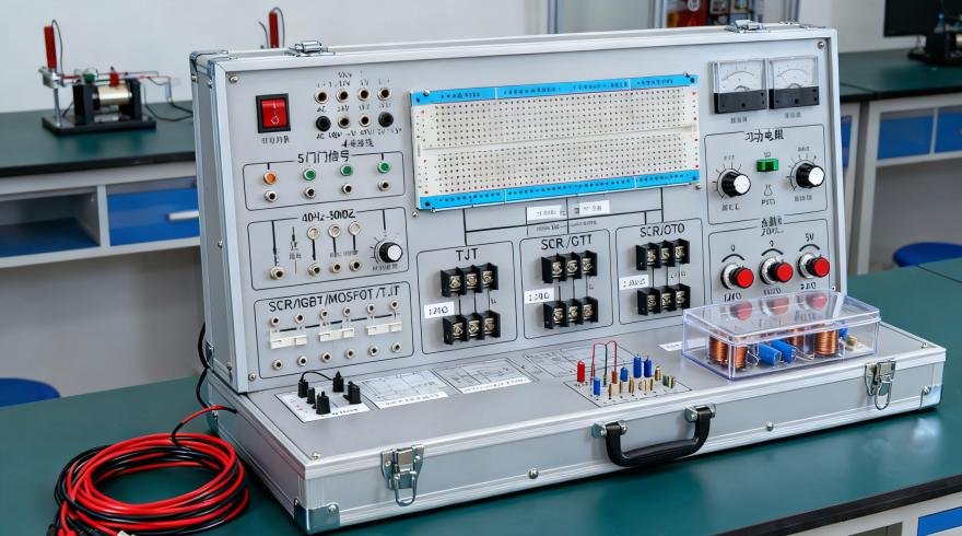
The experiment box consists of an aluminum-wood alloy casing, a switching power supply, common signal sources, and an experimental circuit area. The experimental circuit area adopts a fully open design, allowing for flexible configuration of experimental circuits to meet the teaching and experimental requirements of students at different levels.
I. Technical Specifications
1. Experimental Circuit Power Supply: +5V/2A (one set), ±12V/0.7A (one set), and 1.5~9V (or any value) adjustable (one set). Each circuit has one fuse and short-circuit and reverse protection circuits. The +5V power supply includes overvoltage protection, undervoltage protection, short-circuit alarm, and automatic shutdown functions to ensure the safety of experimental circuit components and personnel.
2. Common Signal Sources
1) Two sets of positive and negative single-pulse generation circuits with level indicators.
2) 1Hz~1kHz continuously adjustable clock circuit.
3) 1Hz~1MHz fixed pulse output in 9 channels, with the 1Hz output featuring an indicator light.
4) 4-channel timing generator and start/stop circuit. 5) 18-channel digital input display circuit with input protection function.
6) 18-channel digital output circuit with built-in display circuit on the output end, clearly showing the output status of the digital signals, and with output protection function.
7) 6-digit seven-segment LED common-anode digital display with built-in BCD code decoding circuit; 2 independent digital tubes, which can be equipped with common-anode or common-cathode digital tubes.
8) 2 sets of BCD code dial switch output circuits with output protection function.
9) Equipped with a 0~10MHz LCD frequency counter.
10) Audio output control circuit composed of a 555 timer circuit, with buzzer and speaker output devices.
3. Testing Tools
1) Provides a three-state digital logic test circuit with audible and visual prompts.
4. Experimental Circuit Area: Independent circuit board design, completely isolated from the experimental signal source, preventing damage to the main unit due to misoperation during wiring of the experimental circuit area. The experimental circuit area is configured as follows:
1) An open experimental area containing 2 IC8 sockets, 9 IC14 sockets, 4 IC16 sockets, 1 IC20 socket, and 1 IC40 locking socket (compatible with IC28/IC24/IC18, etc.). Additional IC14 and IC16 sockets can be added.
2) One each of 100Ω, 4.7K, 10K, and 100K potentiometers.
3) One each of an 8Ω speaker, a buzzer, and a 1×2 switch.
4) A fixed-value component area, including resistors of 10Ω, 100Ω, 470Ω, 1K, 2.7K, 5.1K, and 10K, and capacitors of 0.01uF, 0.033uF, 0.uF, 1uF, 4.7uF/16V, 10uF/16V, and 100uF/16V.
5) Over 300 highly reliable locking anti-overlapping sockets (internally connected to integrated circuit sockets, silver-plated long copper tubes, and fixing components) are provided as experimental connection points and test points. For experimental wiring, simply connect the locking plug wires to each other.
6) Two expansion module circuit access areas: each measuring 155×100mm, with optional fixed circuit experimental modules. Students can conduct innovative exercises to improve their thinking and hands-on abilities.
7) FPGA module: equipped with an EPM2C8T144 chip and a 1M FLASH configuration chip, as well as a download interface. All I/O ports are led out via ribbon cable interfaces, and the accompanying programming software can be updated at any time.
8) Breadboard module (optional): Includes two sets of 350 imported breadboards, with eight self-locking gold-plated sockets for lead-out.
5. Experimental circuit connection: All signal leads use self-locking gold-plated sockets, ensuring no oxidation, a neat appearance, and stable and reliable experimental wire connections.
6. Cabinet: Made of aluminum-wood alloy, environmentally friendly, and with a beautiful and elegant design. Dimensions: 480×360×148MM.
II. Experimental Items Basic Experiments:
1. Gate Circuit Logic Function and Testing Experiment
2. Combinational Logic Circuit (Half Adder, Full Adder, and Logic Operation) Design Experiment
3. Flip-Flops Experiment (I) R-S, D, JK
4. Flip-Flops Experiment (II) Tri-State Output Flip-Flops, Latches
5. Sequential Circuit Testing and Research
6. Integrated Counter and Register Experiment
7. Decoder and Data Selector Experiment
8. Waveform Generation and Monostable Multivibrator Experiment
Extended Experiments:
9. CMOS Gate Circuit Testing Experiment
10. TS and OC Gate Functional Testing and Application Experiment
11. TTL Different Series Chip Performance and Parameter Measurement Experiment
12. Gate Circuit Driving Capability Testing Experiment
13. TTL and CMOS Interconnection Experiment
14. MSI Adder Experiment
15. Race Condition Experiment
16. Sequential Circuit Application Experiment
17. Multiplexer Analog Switch and Its Application Experiment
18. Digital Timer Experiment
19. Voltage Converter Experiment
CPLD Experiment: 1. 3-8 Decoder Experiment
2. 8-3 Encoder Experiment
3. Digital Conversion and Display Circuit
4. Four-Bit Full Adder
5. Four-Bit Parallel Multiplier
6. Design of Basic Flip-Flops
7. Design of 74LS160 Counter Functional Module
8. Controllable Pulse Generator
9. Positive and Negative Pulse Width Digitally Controlled Modulation Signal Generator
10. Sequence Detector (State Machine Design)
11. Memory Design
III. Supporting Accessories and Materials
1. 25 Experimental Wires
2. 1 Power Cord
3. 2 Fuses
4. 1 Experimental Manual
Appendix: Instruments and Meters Required for Using This Experimental Kit
(1) Multimeter
(2) Oscilloscope