- Automobile training equipment series
- Electrical and electronic teaching equipment
- Elevator training series
- Fitter training equipment
- Fluid mechanics experimental equipment
- Hydraulic and pneumatic test bench
- Mechanical teaching equipment
- Robotic automation and mechatronics series
- Welding training equipment

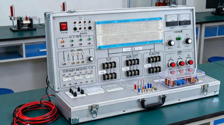
The experiment box consists of an aluminum-wood alloy casing, a high-performance linear power supply, common signal sources, and an experimental circuit area. The experimental circuit area adopts a fully open design, allowing for flexible configuration of experimental circuits to meet the teaching and experimental requirements of students at different levels.
I. Technical Specifications
1.1 Power Supply
1) AC Input: 220V±10%, 50Hz
2) DC Regulated Output: DC: ±12V/0.5A; DC: 5V/1.5A; DC: 3.3V/0.5A, a total of 4 channels. The +5V power supply has overvoltage protection, short-circuit alarm, and automatic shutdown functions to ensure the safety of experimental circuit components and personnel.
1.2 Common Signal Sources
1) Two sets of manual single-pulse circuits: Each set can simultaneously output two positive and two negative pulses, with pulse amplitude at TTL level.
2) Continuous pulse source: 1Hz~100KHz output in 5 adjustable levels. 3) Nine fixed-frequency pulse sources, outputting TTL levels: 1Hz, 2Hz, 10Hz, 100Hz, 1KHz, 10KHz, 100KHz, 500KHz, 1MHz.
1.3 Sixteen-channel level indicator circuit: indicator light on indicates high level ‘1’, indicator light off indicates low level ‘0’. An additional 12-bit level indicator circuit is included for traffic light design.
1.4 Sixteen-channel level input switches: can input low level ‘0’ and high level ‘1’ (positive logic), visually displaying the output status of the switch quantity. The output terminals also have protection functions.
1.5 Digital tube display: Six-digit seven-segment LED common-anode digital display with built-in BCD code decoding circuit for experimental displays such as digital clocks and calendars; two independent digital tubes, which can be fitted with common-anode or common-cathode digital tubes.
1.6 Four sets of BCD code dial switch output circuits, with output terminals having protection functions.
1.7 Logic probes: Red: High level; Green: Low level; Orange: High impedance;
1.8 Provides 5 variable potentiometers, with resistance values of 1K, 10K, 50K, 100K, and 1M respectively.
1.9 Includes an open experimental area for extended experiments and course design.
1) Provides one 40-pin, one 28-pin, one 20-pin, six 16-pin, and eight 14-pin dual-in-line high-reliability round-pin IC socket, accommodating various ICs with pins from 8 to 40.
2) Discrete component insertion area for resistors, capacitors, Zener diodes, diodes, transistors, etc., facilitating expansion.
3) Provides one relay, one buzzer, one push-button switch, and one independent crystal oscillator socket (accommodating active crystals of different values).
1.10 Includes a set of wire test sockets for measuring the continuity of experimental wires.
1.11 Multiple highly reliable locking anti-overlapping sockets (internally connected to integrated circuit sockets, silver-plated long copper tubes, and fixing components) are provided as experimental connection points and test points. For experimental wiring, simply connect the locking plug wires to each other.
1.12 One expansion module circuit access area: Reference size is 155×100mm. A fixed circuit experimental module can be optionally installed. Students can conduct innovative exercises to improve their thinking and hands-on abilities.
1.13 Detachable Experimental Module
1) Discrete component module board, containing resistors of 10Ω, 100Ω, 200Ω, 470Ω, 510Ω, 1K, 1.2K, 1.5K, 4.7K, 5.1K, 10K, 22K, 47K, 100K, 150K, 22MΩ; 20P, 30P, 100P and 100P adjustable, 240P, 300P, 680P, 0.01uF, 0.02uF. Components include: F, 0.047uF, 0.1uF, 10uF/16V, 47uF/16V, 100uF/16V; diodes: 2AK2, 2CK13, 2CK15, IN4007; transistors: 3DG6 and 3DK2; crystal oscillator: 32768HZ; potentiometers: 100K (2), 47K, 15K, 10K, 1K, and 330Ω (1 each), meeting the basic requirements for digital circuit experiments.
1.14 Chassis: Aluminum-wood alloy material, environmentally friendly; reference dimensions: 488×368×152MM.
II. Experimental Projects
Basic Experiments
1. Transistor Switching Characteristics, Limiters, and Clamps
2. Logic Function and Parameter Testing of TTL Integrated Logic Gates
3. Logic Function and Parameter Testing of CMOS Integrated Logic Gates
4. Connection and Driving of Integrated Logic Circuits
5. Design and Testing of Combinational Logic Circuits
6. Decoders and Their Applications
7. Data Selectors and Their Applications
8. Flip-Flops and Their Applications
9. Counters and Their Applications
10. Shift Registers and Their Applications
11. Pulse Distributors and Their Applications
12. Generating Pulse Signals Using Gate Circuits—Self-Excited Multivibrator
13. Monostable Multivibrator and Schmitt Trigger—Pulse Delay and Waveform Shaping Circuits
14. 555 Timer Circuit and Its Applications