- Automobile training equipment series
- Electrical and electronic teaching equipment
- Elevator training series
- Fitter training equipment
- Fluid mechanics experimental equipment
- Hydraulic and pneumatic test bench
- Mechanical teaching equipment
- Robotic automation and mechatronics series
- Welding training equipment

I. Overview
This motor and control system experimental set is meticulously developed based on the requirements of university experimental syllabi, drawing on the strengths of similar products and fully considering the current state and development trends of laboratories. It offers a reasonable structure, comprehensive functionality, excellent reliability, and a high cost-effectiveness compared to similar products.
II. Features
1. Comprehensive Motor and Control System Experimental Set: This set integrates experimental projects covering power electronics, semiconductor conversion, AC/DC speed regulation, AC frequency conversion, motor control, and control theory.
2. Adaptability: It can meet the needs of experimental teaching in various school courses. Its depth and breadth can be flexibly adjusted as needed, allowing for a seamless integration of popularization and advancement based on the progress of teaching. Its modular design allows for easy replacement. Expanding functionality or developing new experiments requires simply adding components, ensuring they remain readily available.
3. Complete Set: From dedicated power supplies, motors, and other experimental components to dedicated experimental connection cables, the set is fully equipped. The performance and specifications of the supporting components are carefully tailored to the needs of the experiments. 4. Highly Intuitive: Each experimental pendant utilizes a separate structure, with component panels and clear diagrams. Each pendant clearly defines its function, making operation and maintenance easy.
5. Highly Scientific: The device occupies a small footprint, saving laboratory space and reducing infrastructure investment. The accompanying small motors are specially designed to simulate the characteristics and parameters of small and medium-sized motors. These motors consume little power, conserving energy, and provide low experimental noise, creating a neat and aesthetically pleasing environment. The experiments are rich in content and well-designed, allowing not only to deepen theoretical knowledge but also to incorporate practical design experiments.
6. Highly Open: The control panel’s power supply is isolated by a three-phase isolation transformer and equipped with voltage and current leakage protection devices to ensure operator safety. Each power output features monitoring and short-circuit protection, ensuring safe and reliable operation. The control panel also features a timer and alarm recorder, providing a unified standard for assessing students’ experimental skills. The meticulous design of the entire device, coupled with reliable component quality and workmanship, results in excellent product performance, all of which creates the conditions for an open laboratory. 7. Advanced Design: This device focuses on the latest devices. While retaining thyristor experiments, it incorporates a wide range of modern power electronics experiments covering the characteristics, driving, and typical applications of these devices. This allows students to gain a thorough understanding of these devices and stay current.
III. Scope of Application
The Motor and Control System Experimental Device covers the required experimental projects for courses such as “Power Electronics Technology (or Semiconductor Converter Technology)”, “DC Speed Regulation”, “AC Speed Regulation”, “Motor Control”, “Electric Drive Automatic Control System”, and “Control Theory” offered by various universities and colleges. IV. Technical Specifications
1. Input Power: Three-phase, four-wire (or three-phase, five-wire, 380V ±10%, 50Hz)
2. Operating Environment: Temperature -10°C to +40°C, Relative Humidity <85% (at 25°C), Altitude <4000m
3. Device Capacity: <1.5KVA
4. Dimensions: 187 × 70 × 158 cm³
V. Basic Equipment
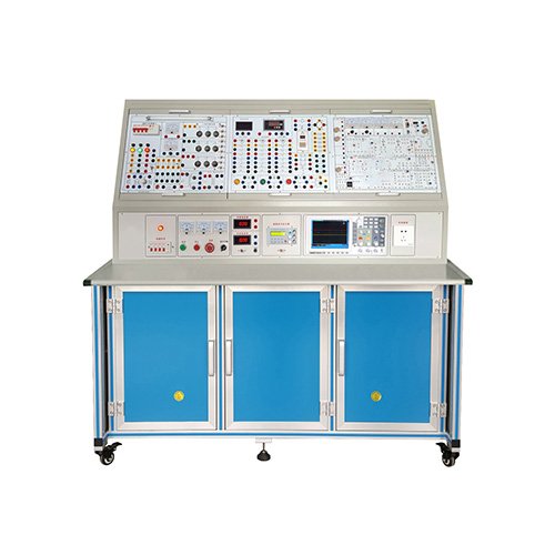
(I) DK01 Power Control Panel (iron, double-layer matte, densely grained, spray-coated structure, aluminum panel)
1. AC Power Supply (both with overcurrent protection)
AC Power Supply: DC speed control mode: three-phase AC 200V/3A.
AC speed control mode: three-phase AC 240V/3A.
2. High-Voltage DC Power Supply
Excitation Power Supply: 220V (0.5A), with output short-circuit protection. 3. Indication and measuring instruments
(1) AC digital voltmeter: can be switched to indicate the three-phase grid input line voltage through the band switch below it;
(2) One true effective value AC digital voltmeter: measuring range 0~500V, automatic range judgment and automatic switching, accuracy 0.5 level, four-digit display, providing voltage indication for the AC speed control system;
(3) One true effective value AC digital ammeter: measuring range 0~5A, automatic range judgment and automatic switching, accuracy 0.5 level, four-digit display, providing current indication for the speed control system;
(4) One DC digital voltmeter: measuring range 0~500V, three-and-a-half digit display, input impedance 10MΩ, accuracy 0.5 level, providing voltage indication for the speed control system;
(5) One DC digital ammeter: measuring range 0~5A, three-and-a-half digit display, accuracy 0.5 level, providing current indication for the speed control system. 4. Personal safety protection system
(1) A set of three-phase isolation transformers: The three-phase power supply first passes through the three-phase leakage protector, and then through the key switch and contactor to the isolation transformer, so that the output is isolated from the power grid (floating design), which plays a certain protective role in personal safety.
(2) Current type leakage protection device: If there is leakage in the control panel, the leakage current exceeds a certain value, and the power supply is cut off.
(3) Experimental connection wires and sockets: Strong and weak current connections and sockets are separated and cannot be mixed.
(4) Strong current connection wires and sockets adopt a fully enclosed process, which is safe, reliable and prevents electric shock.
5. Other facilities of the control panel
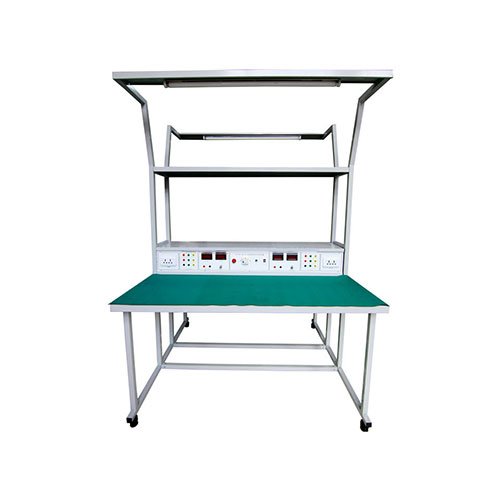
In the large groove on the front of the control panel, there are two steel pipes for hanging experimental components. There is a 3-core socket at the bottom of the groove, and the power supply of the hanging components is provided by these sockets. There are single-phase three-pole 220V power sockets and three-phase four-pole 380V power sockets on both sides of the control panel. There is also a 40W fluorescent lamp for lighting the experimental table. (II) DK02 Laboratory Table
The table features a double-layered, matte, densely textured plastic-sprayed iron construction. The tabletop is constructed of fireproof, waterproof, and wear-resistant high-density board. Its sturdy construction and enclosed rectangular shape create an elegant and elegant design. It features two large drawers and doors for storing tools, accessories, and documents. The tabletop is designed to accommodate a power control panel and provides a spacious and comfortable work surface. The table also features four universal casters and four fixed adjustment mechanisms for easy movement and securement, facilitating laboratory layout. (III) Experimental Equipment
1. DQ03-1 Fixed Motor Guide Rail, Speed Measurement System, and Intelligent Digital Tachometer
2. DQ27 Three-Phase Adjustable Resistor (900Ω × 2/0.41A per set)
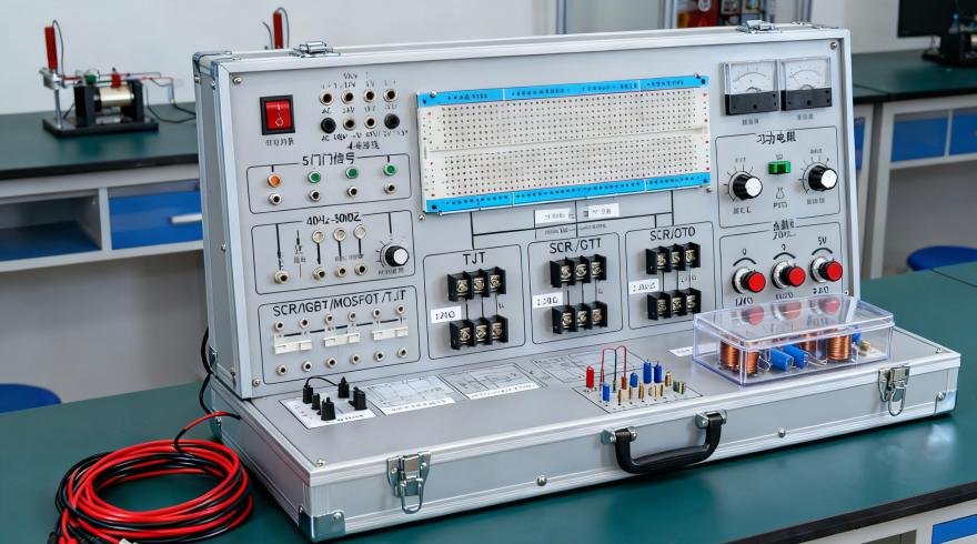
3. DK03 Thyristor Main Circuit
Provides 12 5A/1000V thyristors, each equipped with RC snubber and fuse protection. The thyristors can be triggered by an external trigger signal (with a trigger pulse input interface), enabling efficient completion of design experiments. Also provided are a ±300V precision pointer DC voltmeter with a mirror, a ±2A precision Class 1.0 precision DC ammeter with a mirror, and a set of smoothing reactors.
4. DK04 Three-Phase Thyristor Trigger Circuit
Provides a three-phase trigger circuit, power amplifier circuit, pulse transformer, etc. for use with the DK03. 5. DK05 Thyristor Trigger Circuit Experiment
Provides unijunction transistors, sawtooth wave synchronous shift, sine wave synchronous shift trigger circuits, KC05 single-phase AC voltage regulator, Siemens TCA785 integrated trigger circuit, etc.
6. DK06 Motor Speed Control Experiment (I)
Provides the following modules: Current Feedback and Overcurrent Protection (FBC+FA), Setter (G), Speed Converter (FBS), Speed Regulator (ASR), Reverser (AR), Current Regulator (ACR), etc.
7. DK10 Adjustable Resistor and Capacitor Box
Provides three sets of AC63V adjustable capacitors with an adjustment range of 0.1 to 11.37µF and two sets of 0 to 999kΩ decimal adjustable resistors. These are used in the feedback loops of the current and speed regulators, allowing for flexible adjustment of the regulator’s gain and integration time. 8. DK11 Single-Phase Voltage Regulation and Adjustable Load
Provides a 0-250V/0.5kVA single-phase AC autovoltage regulator to provide an adjustable power source for corresponding experiments; a rectifier and filter circuit, and a 0-90Ω/1.3A (series) or 0-45Ω/2.6A (parallel) ceramic disc adjustable resistor to provide an adjustable resistive load for corresponding experiments.
9. DK12 Transformer Experiment
Provides a three-phase core-type transformer (with two sets of secondary windings, primary and secondary winding voltages of 127V/63.6V/31.8V) for experiments with asynchronous motor cascade speed regulation and three-phase and single-phase bridge active inverter circuits. Also included are modules for a three-phase uncontrolled rectifier circuit.
10. DK14 Single-Phase AC/DC Frequency Conversion Principle
Developed based on the content of “Power Electronics Technology” (4th edition), edited by Wang Zhaoan and Huang Jun, a national key textbook for general higher education during the “Ninth Five-Year Plan” period. This system demonstrates the principles of AC/DC/AC frequency conversion. It primarily allows students to understand the generation of SPWM sinusoidal pulse-width modulation signals, the characteristics and usage of IGBT-specific integrated driver chips, and the ability to complete the following experimental projects:
1) The SPWM wave generation process;
2) The operation and waveforms of the AC/DC/AC frequency conversion circuit under different loads (resistance, inductance), and the impact of operating frequency on the circuit’s operating waveforms;
3) The operating characteristics of the IGBT-specific integrated driver chip.
11. DK17 Dual Closed-Loop H-Bridge DC/DC Converter DC Speed Control System
This system achieves speed control of a reversible DC separately excited motor by controlling the triggering of the IGBTs on the four bridge arms. It consists of three main components: the main circuit, the control circuit, and the regulation circuit. The main circuit consists of a DC power supply and four IGBT tubes; the control circuit part is composed of a dedicated chip to generate PWM pulse waves. The four control pulses generated by the PWM wave pulse generator drive the IGBT tubes of the four bridge arms respectively; the regulation part is composed of two PI regulators, and the feedback loop composed of the speed loop and the current loop is used to stabilize the motor speed at a given speed. The experimental projects that can be completed in this experimental box are: (1) full-bridge DC/DC conversion circuit experiment (2) dual closed-loop reversible DC pulse width speed regulation experiment.
12.DK06-1 Motor Speed Control Circuit (II)
Provides the following modules: zero level detection (DPZ), torque polarity identification (DPT), logic control (DLC).
13. DQ07-1 DC Generator (DC220V, 240W, n=1500RPM)
14. DQ09 DC Shunt Motor (Un=DC220V, IN=1.1A, PN=185W, n=1500RPM, Insulation Class E)
15. DQ11 Three-Phase Wire-Wound Asynchronous Motor (AC220V, Y Connection, Speed 1380RPM, Power 100W, Current 0.6A, Insulation Class E)
16. GDQ12 Wire-Wound Asynchronous Motor Starting and Speed Regulating Resistor Box
Provides a set of rotor starting and speed regulating resistors for three-phase wire-wound asynchronous motors with sizes 0, 2, 5, and 15.
17. GDK28 Three-Phase Asynchronous Motor Variable Frequency Speed Control System
Provides one Mitsubishi FR-D720 variable frequency speed control system with panel-mounted terminals and a 1K ohm speed potentiometer.
18. Experimental Connection Cables:
The Motor and Control System Experimental Device is equipped with two different types of experimental connection cables, tailored to the specific experimental projects. The high-current portion utilizes a highly reliable, sheathed, pistol-plug connection cable (eliminating any risk of electric shock). The cable is made of oxygen-free copper, drawn from strands as thin as a hair, for exceptional flexibility. The cable is insulated with a nitrile polyvinyl chloride (PVC) layer, offering advantages such as flexibility, high voltage resistance, high strength, resistance to hardening, and excellent toughness. The plug is constructed of solid copper with a beryllium light copper spring, ensuring safe and reliable contact. The low-current portion utilizes a flexible, bare beryllium light copper connection cable. Both types of cable can only be used with corresponding sockets, significantly enhancing experimental safety and reliability.
VI. Experiments Available with This Device
(I) Power Electronics Technology Experiments
1. Unijunction Transistor Trigger Circuit
2. Sawtooth Wave Synchronous Phase-Shift Trigger Circuit Experiment
3. Single-Phase Half-Wave Controlled Rectifier Circuit Experiment
4. Single-Phase Bridge Half-Controlled Rectifier Circuit Experiment
5. Single-Phase Bridge Full-Controlled Rectifier and Active Inverter Circuit Experiment
6. Three-Phase Half-Wave Controlled Rectifier Circuit Experiment
7. Three-Phase Bridge Half-Controlled Rectifier Circuit Experiment
8. Three-Phase Half-Wave Active Inverter Circuit Experiment
9. Three-Phase Bridge Full-Controlled Rectifier and Active Inverter Circuit Experiment
10. Single-Phase AC Voltage Regulator Circuit Experiment
11. Three-Phase AC Voltage Regulator Circuit Experiment
(II) Typical Power Electronic Device Circuit Experiments
1. Single-Phase Sine Wave Pulse Width Modulation (SPWM) Inverter Circuit Principle Experiment
2. Full-Bridge DC/DC Converter Circuit Experiment
(III) DC Motor Speed Control Experiment (DC Motor Motion Control System)
1. Debugging the Main Units of a Thyristor DC Speed Control System
2. Single-Speed Closed-Loop DC Speed Control System with Current Cutoff Negative Feedback Experiment
3. Speed and Current Dual Closed-Loop DC Speed Control System Experiment
4. Logic-Free Reversible DC Speed Control System Experiment
5. Speed and Current Dual Closed-Loop Reversible DC PWM Speed Control System (H-Bridge, IGBT)
(IV) AC Motor Speed Control System Experiment (AC Motor Motion Control System)
1. Dual Closed-Loop Three-Phase Winding Asynchronous Motor Voltage and Speed Control System Experiment
2. Dual Closed-Loop Three-Phase Winding Asynchronous Motor Series-Pole Speed Control System Experiment
3. Variable Frequency Speed Control System Experiment