- Automobile training equipment series
- Electrical and electronic teaching equipment
- Elevator training series
- Fitter training equipment
- Fluid mechanics experimental equipment
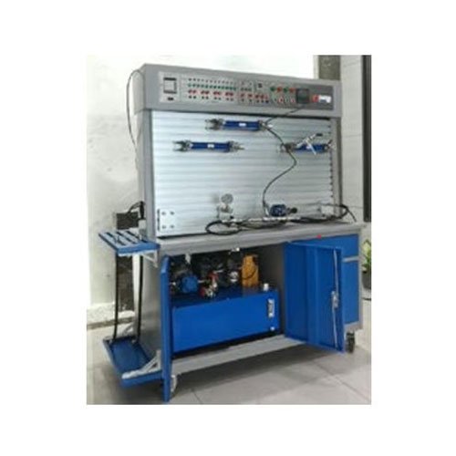
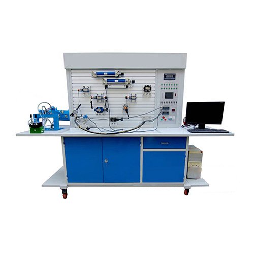
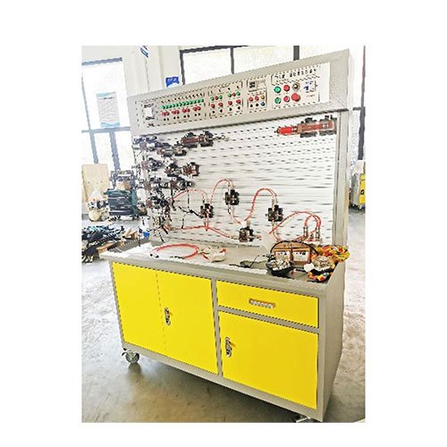
- Hydraulic and pneumatic test bench
- Mechanical teaching equipment
- Robotic automation and mechatronics series
- Welding training equipment

Technical Parameters:
1) Input Power Voltage: Three-wire/four-wire AC220-380V±10% 50HZ;
2) Module and Component DC Voltage: DC24V, 4.5A;
3) Operating Environment: Temperature -10℃~+40℃, Relative Humidity <85% (25℃), Altitude <4000m;
4) Product Dimensions: Approximately 2100*750*1800mm (L×W×H);
5) Weight: Approximately 360kg;
6) Hydraulic Pump Set: Equipped with a vane pump and drive motor; nominal tank capacity 45L; pump power 1.5KW, rated pressure 7 MPa, flow rate 10L/min at 1450r/min, nominal displacement 6.67mL/r, volumetric efficiency 90%; 7) Air Pump: The air pump is a medical-grade silent air compressor with a noise level <45 decibels, rated pressure: 0.8 MPa, flow rate: 55 L/min, volume: 8 L, and power: 550 W.
System Composition: The device mainly consists of a training workbench, a feeding unit, a conveying unit and clamping unit, an excavator unit, a robotic arm unit, a power unit, and a control unit.
The modular and flexible configuration fully reflects the diverse functions, simplified operation, safe use, and diversified course experiments of this experimental system. Based on the teaching syllabus and experimental outline of higher education and vocational education, and adhering to the principles of not deviating from the teaching syllabus, broad professional coverage, and comprehensive functions, this comprehensive experimental system is professionally designed and developed. The modules involved are as follows (see list for module configuration details):
Module 1: Power Control Unit DB-1;
Module 2: Relay Unit DB-2;
Module 3: Programmable Controller Main Unit DB-3;
Module 4: Sensor Application Unit DB-4;
Module 5: Programmable Control Input Board DB-5;
Module 6: Hydraulic and Pneumatic Training Module DB-6;
Module 7: Engineering Machinery Training Unit DB-7;
Module 8: Robot Arm Training Unit DB-8;
Module 9: Loading Training Unit DB-9;
Completable course experiments include:
Task 1: Equipment Installation and Adjustment
(1) Installation and adjustment of automated mechanisms such as handling, conveying, and clamping;
(2) Positioning, installation, and adjustment of electrical components such as PLCs, relays, leakage circuit breakers, and switching power supplies;
(3) Installation and adjustment of pneumatic components;
(4) Installation and adjustment of hydraulic components. Task Two: Hydraulic Transmission System Diagram Reading and Piping Installation
This task involves reading diagrams and installing hydraulic pipelines for hydraulic transmission systems such as hydraulic presses, excavator feed systems, and hydraulic pump stations.
Task Three: Pneumatic System Diagram Reading and Piping Installation
This task involves reading diagrams and installing air pipes for pneumatic systems such as pressure regulation, reversing, speed regulation, and sequential action control.
Task Four: Electrical Control Circuit Schematic Design and Wiring
This task includes designing the electrical schematic diagram of the automatic control system based on the workflow and control requirements, and arranging and connecting the control system circuits according to the schematic diagram.
Task Five: Programming and Debugging
This task involves writing and debugging PLC programs and relays for various electrical control circuits.
Task Six: Overall Debugging and Operation of Mechatronic Equipment
This task includes setting PLC control parameters, and debugging and operation of mechanical mechanisms, hydraulic transmission and pneumatic systems, relays, and the PLC electrical control system. V. Requirements for Hydraulic and Pneumatic Auxiliary Teaching Resources (One set for the entire laboratory)
1. PLC Teaching Resources
(1) The software teaching content should be consistent with the PLC series products配套 with the equipment;
(2) Provide no less than 50 learning projects;
2. PLC Training Software
(1) Provide relevant consolidation exercises, requiring the exercise content to correspond to the PLC learning software.
(2) Each question should have an automatic result evaluation function or a training step prompt function.
3. Hydraulic Transmission Simulation System
The hydraulic simulation control software is a hydraulic simulation control system developed based on KingSCADA, containing 20 typical hydraulic circuit controls and demonstrations. It vividly displays the flow direction of hydraulic oil, the working state of the internal valve cores of various hydraulic valves, the working process of the oil cylinder, and the working principle of the gear pump on the screen. More than 10 of them can be directly connected to the hardware to control the operation of the hardware system and monitor the entire working process. The hydraulic simulation control system includes:
1. Pressure regulation circuit – two-stage pressure regulation circuit;
2. Pressure regulation circuit – pressure reducing valve pressure reducing circuit;
3. Two-position two-way solenoid directional valve unloading circuit;
4. Two-position four-way solenoid directional valve switching circuit;
5. Three-position four-way solenoid directional valve switching circuit;
6. Manual directional valve switching circuit (no hardware control, only demonstration of the manual directional valve working principle);
7. Inlet throttling speed control circuit;
8. Return throttling speed control circuit;
9. Bypass throttling speed control circuit;
10. Limit switch controlling two three-position four-way solenoid directional valves switching circuit;
11. Sequential action circuit controlled by a sequence valve (limit switch);
12. Speed switching circuit: fast-slow speed switching circuit;
13. Speed switching circuit: fast-slow-working speed switching circuit (one type of throttle valve in series); 14. Speed switching circuit: Fast-Slow-Working speed switching circuit (parallel throttle valves)
15. Locking circuit;
16. Throttle valve control synchronization circuit;
17. Differential circuit, etc.
4. Pneumatic Technology Teaching Resources
(1) Basic knowledge of pneumatic technology: Overview of pneumatic technology, composition of pneumatic systems, basic properties of air, basic knowledge of fluid mechanics,
Air humidity.
(2) Air source system: Air compressor, aftercooler, air tank.
(3) Air handling unit: Automatic drainer, air filter, dryer, air combination components.
(4) Actuating elements: Standard cylinder, swing cylinder, other types of cylinders.
(5) Pneumatic control elements: Pressure control valve, flow control valve, directional control valve, electro-proportional valve.
(6) Vacuum system: Vacuum generating equipment, vacuum air valve, vacuum pressure switch, air filter, application examples. (7) Pneumatic auxiliary components: lubricator, muffler, magnetic switch, pressure switch, flow switch, pipes and connectors.
(8) Pneumatic circuit simulation: reversing circuit, pressure circuit, speed circuit, other circuits.
(9) Management, maintenance and troubleshooting: management, maintenance, troubleshooting, repair.
(10) Basic knowledge practice and test: basic pneumatic theory, comprehensive test questions.
5. Hydraulic circuit connection simulation training system
(1) The appearance and interface layout of the hydraulic component modules in the system are consistent with the actual hydraulic components matched to the device;
(2) It can complete the simulated connection and operation simulation experiment of hydraulic pipelines. Hydraulic Experiment Projects: (Over 20 hydraulic system experiments that can be freely built and combined)
Experiment 1: Primary Pressure Regulating Circuit;
Experiment 2: Secondary Pressure Regulating Circuit;
Experiment 3: Basic Directional Control Valve Circuit;
Experiment 4: Speed Control Circuit;
<1> Bypass Throttling Speed Control Circuit;
<2> Inlet Throttling Speed Control Circuit;
<3> Return Throttling Speed Control Circuit;
<4> Speed Control Valve Inlet (Bypass or Return) Speed Control Circuit;
Experiment 5: Basic Unloading Circuit;
Experiment 6: Pressure Reduction Circuit;
Experiment 7: Hydraulic Pressure Holding Circuit;
Experiment 8: Hydraulic Locking Circuit;
Experiment 9: Hydraulic Differential Circuit;
Experiment 10: Limit Switch Control Sequential Action Circuit;
Experiment 11: Sequence Valve Control Sequential Circuit;
Experiment 12: Dual Cylinder Loading and Top Control Circuit;
Experiment 13: Hydraulic Delay Control Circuit;
Experiment 15: Hydraulic Synchronization Circuit;
Experiment 16: Cylinder Displacement Control Experiment; Experiment 17: Automatic Reciprocating Control of a Hydraulic Circuit;
Experiment 18: Two-Stage Speed Shift Control Circuit;
Experiment 19: Multi-Stage Speed Shift Control Circuit;
Experiment 20: PLC Counting and Timing Automatic Control Hydraulic Circuit;
Experiment 21: Variable Frequency Volumetric Speed Regulation Circuit Experiment.
Pneumatic Experiment Projects: (Over 20 projects can be built and tested)
Experiment 1: Reversing Circuit of a Single-Acting Cylinder;
Experiment 2: Reversing Circuit of a Double-Acting Cylinder;
Experiment 3: Speed Regulation Circuit of a Single-Acting Cylinder (One-Way, Two-Way);
Experiment 4: Speed Regulation Circuit of a Double-Acting Cylinder (Inlet Control, Outlet Control);
Experiment 5: Speed Switching Circuit;
Experiment 6: Buffer Circuit;
Experiment 7: Interlock Circuit;
Experiment 8: Overload Protection Circuit;
Experiment 9: Unloading Circuit;
Experiment 10: Single-Cylinder Single Reciprocating Control Circuit;
Experiment 11: Single-Cylinder Continuous Reciprocating Control Circuit;
Experiment 12: Double-Cylinder Sequential Action Circuit;
A. Using a Stroke Valve;
B. Using Electrical Switches (Magnetic Switch, Limit Switch, Proximity Switch);
C. Using a Pressure Relay;
Experiment 13: Double-Cylinder Linkage Circuit;
Experiment 14: Secondary Pressure Control Circuit;
Experiment 15: High-Low Pressure Conversion Circuit;
Experiment 16: Counting Circuit;
Experiment 17: Delay Circuit; Experiment 18: Application Circuit of Logic Valves (NOT, OR, AND);
Experiment 19: Two-Handed Operation Circuit;
Experiment 20: Control Experiment Combining PLC and Pneumatics.
Comprehensive Control Experiments:
1. Variable Frequency Volumetric Speed Regulation Experiment;
2. PLC Control of Reciprocating Positioning in a Hydraulic System;