- Automobile training equipment series
- Electrical and electronic teaching equipment
- Elevator training series
- Fitter training equipment
- Fluid mechanics experimental equipment
- Hydraulic and pneumatic test bench
- Mechanical teaching equipment
- Robotic automation and mechatronics series
- Welding training equipment

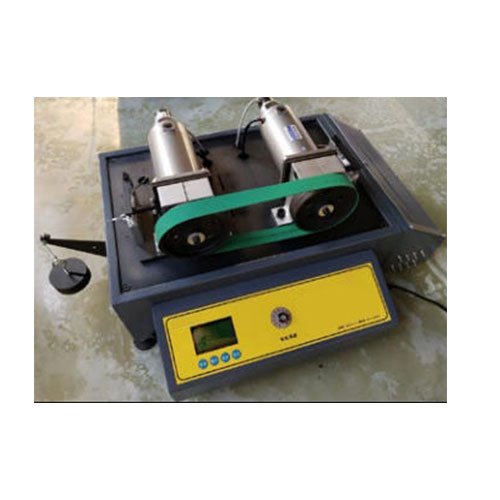
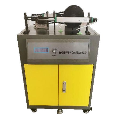
The experimental platform uses a small diesel engine, the most typical flywheel speed regulation system in engineering applications, as the experimental object. Innovative designs have been made to its components, creating an innovative combined experimental platform with adjustable impact force, flywheel inertia, and changeable unit working resistance modes. This allows the experimental test object to be changed according to the working resistance mode. The dynamics of the mechanical system are analyzed and studied by measuring the smooth motion law and starting and braking characteristics of the flywheel under different working resistance modes.
I) Main Features
(1) The experimental platform adopts the structure of a small diesel engine, the most typical flywheel speed regulation system in engineering applications, and the unit’s working resistance mode can be changed.
(2) The stiffness of the impact spring is variable. By changing the stiffness of the impact spring, the magnitude of the impact force (working resistance) can be changed, that is, the magnitude of the equivalent resistance torque, one of the basic parameters of flywheel speed regulation.
(3) A photoelectric encoder is installed on the flywheel spindle: it can accurately measure the starting and stopping time of the flywheel during starting and stopping processes; and the speed fluctuation curve during starting and braking processes. (4) Using a photoelectric encoder, the angular velocity variation, maximum angular velocity ωmax, minimum angular velocity ωmin, average angular velocity ωm, and rotational unevenness δ value of the system during stable motion can be measured.
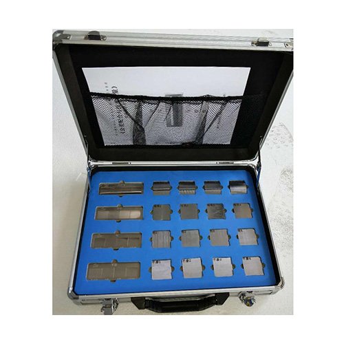
(5) The flywheel on the experimental platform is designed in the form of a flywheel ring for easy disassembly. Based on the measured maximum surplus/deficit work Wy, average angular velocity ωm, and rotational unevenness δ requirements, flywheels with different equivalent moments of inertia are selected or designed and fabricated, and tested on the experimental platform to verify the results, comparing them with theoretical calculations. II. Experimental Items:
1. Stable speed fluctuation test of the unit in non-operating state
2. Speed fluctuation test of the unit in operating state
3. Speed fluctuation test of the unit during starting and braking
III. Main Parameters:
1. Input power supply voltage: AC220V±10% 50HZ;
2. Control voltage: Safety control voltage—DC24V, 4.5A, with automatic short-circuit protection function;
3. Operating environment: Temperature -10℃~+40℃, relative humidity <85% (25℃), altitude <4000m (dustproof and moisture-proof); 4. Motor power: ≥150W; 5. Speed: 1400rpm; 6. Motor torque sensor range: 0~100N, accuracy: 0.05%; 7. Flywheel angular displacement sensor: Output voltage: 0-5V, pulse count: 360 pulses/cycle; 8. Product dimensions: Length × Width × Height = Approximately 480×480×760(mm); 9. Net weight: approximately 65kg.