- Automobile training equipment series
- Electrical and electronic teaching equipment
- Elevator training series
- Fitter training equipment
- Fluid mechanics experimental equipment
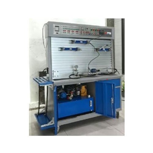
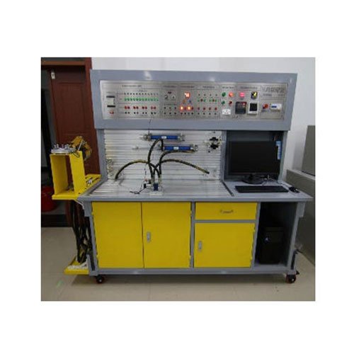
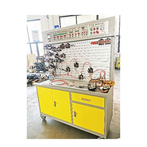
- Hydraulic and pneumatic test bench
- Mechanical teaching equipment
- Robotic automation and mechatronics series
- Welding training equipment

★I. Test Bench Main Parameters
1. Test Bench Power Supply: National Standard Industrial Power—AC380V, 50Hz;
2. Test Bench Control Voltage: Safety Control Voltage—DC24V;
3. Total System Power: <=5kW;
4. Hydraulic Pump Unit: Equipped with a hydraulic oil pump and drive motor, with a nominal oil tank capacity of 45L; pump unit power: 1.5kW, rated pressure 6.3 MPa, nominal displacement 6.67 mL/r, volumetric efficiency 90%;
5. System Safe Operating Pressure: P <=6.3 MPa;
6. Test Bench Dimensions (mm): 2300 × 750 × 1820;
7. Test Bench Weight: Approximately 300kg
II. Main Functions of the Laboratory Bench
1. All hydraulic valves must utilize advanced Bosch Rexroth hydraulic components, with performance parameters fully meeting the syllabus requirements and industrial application standards, referencing design standards such as JB/JQ20233-88. The bench must be compatible with the existing equipment in the laboratory. The overlap dimensions are universal, hydraulic connectors are interchangeable, and the valve bottom oil block hooks match the existing equipment. A free one-time technical service is provided for older equipment, including but not limited to repair, cleaning, and maintenance.
2. The excavator mechanism is used as a supplementary actuator system. For durability, the excavator’s boom, arm, and bucket must not be made of hard plastic or plexiglass. Instead, they must be constructed of all-metal steel plates, scaled to exacting specifications, and featuring exquisite workmanship. (A demonstration video showcasing the excavator’s mechanical structure and operating process will be provided at the bidding site.)
3. The electrical control system must utilize the new-generation RLAY-OUT-1 integrated circuit board (an integrated circuit, not a data acquisition card). This board features over 10 built-in inputs and outputs, eliminating the need for complex wiring. This ensures a more stable overall electrical system and facilitates subsequent maintenance and troubleshooting.
4. The equipment offers a variety of control methods, integrating various control technologies, including mechanical control, relay control, PLC automation, host computer configuration control, and compound control.
5. The software enables visual simulation of hydraulic control circuits, directly reflecting the operating status of the hydraulic circuit, PLC operating status, and the internal structure of each hydraulic component. It also communicates directly with the host computer for real-time control of the hardware circuit. This multi-disciplinary system modeling hydraulic software enables multi-dimensional virtual design and assembly of integrated mechatronic systems. 6. The data acquisition system is efficient and stable, enabling intelligent data acquisition, analysis, processing, digital display, automatic curve generation, and real-time monitoring for digital valve characteristic tests and control experiments. The industrial simulation actuators involved must have an industrial simulation structure and an automatic fault detection and analysis system.
7. Practical Training Functions:
a. Standard series hydraulic component operating principle understanding experiment
b. Hydraulic component performance test experiment
c. Hydraulic resistance characteristic performance test experiment
d. Hydraulic circuit configuration screen demonstration and control experiment; Basic hydraulic transmission circuit experiments: Basic pressure control circuits (single-stage pressure regulation, multi-stage pressure regulation, pressure reduction, balancing, pressure holding, and pressure relief circuits), speed control circuits (throttle valve, speed control valve, differential, volumetric, and compound speed control circuits), one-way synchronization circuits (synchronization circuits controlled by throttle valves and speed control valves), directional control circuits (reversing circuits controlled by reversing valves), sequential action circuits (sequential action circuits controlled by pressure relays, limit switches, and sequence valves), and locking circuits. (Lock circuit controlled by hydraulic one-way valve, O/M type reversing valve, one-way valve, etc.);
e. Hydraulic circuit experiment:
(1) Pressure control circuit experiment;
A. Pressure limiting circuit:
B. Voltage changing circuit:
C. Unloading circuit:
D. Voltage stabilizing circuit:
E. Pressure relief circuit:
F. Pressure reducing circuit
(2) Speed control circuit experiment;
A. Speed regulating circuit:
B. Synchronous circuit:
(3) Direction control circuit experiment;
A. Reversing circuit:
B. Locking circuit:
C. Sequential circuit:
D. Balance circuit:
E. Buffer circuit:
(4) Other expandable hydraulic circuit experiment types are as many as dozens of types
f. Intelligent data acquisition system experiment: Real-time experimental data acquisition, analysis, processing, real-time display, automatic generation of experimental curves, printing and other functions of various hydraulic sensor data.
8. Main technical parameters of data acquisition system: Real-time experimental data acquisition, analysis, processing, real-time display, automatic generation of experimental curves, printing and other functions of pressure, flow, power speed, temperature and other data. Computer configuration should be no less than: I5 host, 4G memory, 500G hard drive, 21-inch LCD monitor, mainstream brand machine, equipped with data acquisition card and a full range of sensor hardware. (The equipment must enable software and hardware communication and real-time control.)
9. Cultural Wall Construction: (Fabric materials may not be used. Bidders must bring a sample to the site.) Display content must be relevant to the teaching content of this equipment. Display content must include at least five images, including color, high-definition images, virtual 3D cross-sections, and a text description. Display content must include a schematic diagram of the axial clearance compensation device, a schematic diagram of the clearance compensation principle for the floating sleeve type, a schematic diagram of the clearance compensation principle for the floating side plate type, a schematic diagram of the clearance compensation principle for the flexible side plate type, installation methods for a double-acting single-piston hydraulic cylinder, cylinder body mounting, piston-cylinder mounting, the operating principle of a gear pump, oil trapping in a gear pump, dead volume diagrams, minimum and maximum dead volume, oil trapping relief grooves in a gear pump, symmetrical double rectangular relief grooves, asymmetrical double rectangular relief grooves, and simplified diagrams for calculating differential pressure and shear flow leakage. Dimensions must not exceed 0.5*0.7m-1.0*0.7m, framed with an organic transparent backing and a translucent outer surface (such as acrylic), the overall appearance should be crisp and elegant. Display content must include type, schematic, operating characteristics, and schematic diagram.
10. Hydraulic valve and pump component simulation resources, each unique and without overlapping content.
No less than 100 types (must include features such as dynamics and 3D explosions, and on-site demonstrations must be provided)