- Automobile training equipment series
- Electrical and electronic teaching equipment
- Elevator training series
- Fitter training equipment
- Fluid mechanics experimental equipment
- Hydraulic and pneumatic test bench
- Mechanical teaching equipment
- Robotic automation and mechatronics series
- Welding training equipment

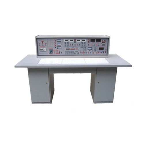
I. Innovations of the Integrated Experimental Equipment for Electrical Engineering, Electronics, Digital Electronics, and Analog Electronics:
(1) The experimental enclosures, functional modules, and experimental table frame are all made of aluminum alloy in a single casting, resulting in a uniform, aesthetically pleasing, and elegant appearance.
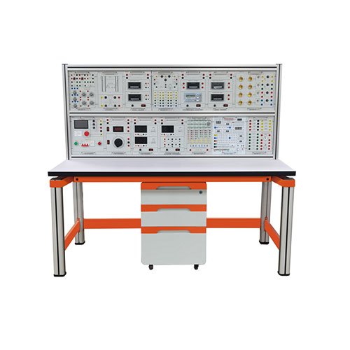
(2) Modular Design: Highly expandable and easy to maintain. All experimental enclosures and power supply functional modules adopt a detachable and freely combinable design, facilitating expansion and functional upgrades. This also solves the problem of difficult overall machine maintenance; simply sending the small enclosure back to the manufacturer allows for quick and convenient solutions to related issues.
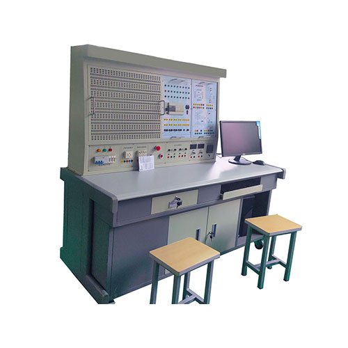
(3) Dustproof Curtain Design: When the experimental device is not in use, pulling down the dustproof curtain can extend the lifespan of the experimental device. (4) Improved power supply safety and reliability: The three-phase power supply adopts microelectronic control, which can effectively suppress electric sparks and explosions during three-phase short circuits, so that students are no longer afraid of electric sparks and explosions; the overload current is adjustable, with a two-digit digital display, an adjustment accuracy of 0.1, and a maximum overload current of 9.9A; the number of overloads can be queried and can be saved after power failure, which is convenient for teaching management; the strong and weak current sockets are isolated from each other, and the strong current uses a high-safety sheathed socket to improve safety. (Optional)
(5) Designed wireless remote control function for the power supply: It adopts high-frequency electromagnetic wave wireless transmission, which has a long operating distance and strong anti-interference ability. (Optional)
II. Functions of the comprehensive experimental equipment for electrical engineering, electronics, digital circuits, and analog circuits:
1. Safety protection system: It is equipped with short circuit, overload protection, emergency stop, and leakage protection.
2. Three-phase 380V output, DC 220V output, and 3 sets of 220V sockets. 3. Dual 24V Adjustable DC Regulated Power Supply: Two coarse adjustment output levels, fine adjustment with 1V precision; features soft protection and cutoff protection; includes positive and negative polarity indicator LEDs to prevent reverse polarity connection.
4. AC Power Supply: Dual 9V, Dual 12V, Dual 18V outputs, 0~240V AC output.
5. Two sets of single pulse outputs.
6. DC Regulated Power Supply: ±12V, ±5V four sets of DC regulated power supply outputs.
7. 2M Function Signal Generator:
1) Waveforms include sine wave, square wave, and triangle wave.
2) Attenuation levels: 0—20db—(40db).
3) Includes one frequency meter with a six-digit display, measurement range up to 0-8M, supports external measurement.
4) Constant Current Source: 500mA adjustable constant current source with two output levels, three-digit display, adjustable precision of 1mA. 8. Dual small signal source: Two continuously adjustable outputs from -5V to +5V, with an adjustment accuracy of 0.1%; Two continuously adjustable outputs from -0.5V to +0.5V, with an adjustment accuracy of 0.1%.
9. AC/DC digital millivoltmeter: Test range 2mV to 200V (RMS), 0.5% accuracy. (Optional)
10. AC/DC digital milliammeter: Test range 2mA to 200mA (RMS), 0.5% accuracy.
III. Experimental Items of the Integrated Electrical Engineering, Electronic Engineering, Digital Electrical Engineering, and Analog Electrical Engineering Experimental Equipment:
1. Basic Electrical Engineering Experiments:
1) Use of basic electrical instruments and calculation of measurement errors
2) Verification of Kirchhoff’s laws
3) Measurement of the volt-ampere characteristics of circuit components
4) Verification of the superposition principle
5) Equivalent transformation of voltage sources and current sources
6) Thevenin’s theorem
7) Two-port network testing
8) Study of controlled sources VCVS, VCCS, CCVS, and CCCS
9) Observation and measurement of typical electrical signals
10) Response testing of first-order RC circuits
11) Determination of impedance characteristics of R, L, and C components
12) RC frequency selective network characteristic test
13) Mutual inductance circuit observation
14) Single-phase iron core transformer characteristic test
15) Three-phase AC circuit voltage and current measurement
16) Three-phase circuit power measurement
17) Single-phase electricity meter calibration
18) Power factor and phase sequence measurement
19) Negative impedance transformer
20) Rotary circuit
21) Ammeter range extension
22) Voltmeter range extension
23) Series and parallel resistor circuits
24) Current transformer
25) Study of R, L, C series resonant circuits
26) Study of second-order dynamic circuit response
27) External characteristics of power supply
28) Improvement of power factor in single-phase AC circuits
29) Series, parallel, and mixed connection of resistors
30) Resistor voltage divider
31) Load maximization 32) Power Conditions
33) Wheatstone Bridge
34) Determination of Filament I-V Characteristics
35) Staircase Switch Two-Place Control
36) RL Series Circuit
37) RC Series Circuit
38) RCL Parallel Circuit
39) Study of Capacitor Charging and Discharging
40) Role of Capacitors in AC and DC Circuits
41) Role of Inductors in AC and DC Circuits
42) Single-Phase AC Circuit Experiment
43) Fluorescent Lamp Circuit
44) Principle of Welding Transformer
45) Transient Process of First-Order RC Circuit
46) Transient Process of First-Order RL Circuit
47) Role of Magnet in Coil
48) Mutual Inductance Phenomenon
49) Self-Inductance Phenomenon of Current Flow and De-current Flow
50) Reverse Series Connection of Magnetic Coupled Coils
2. Basic Electronic Experiments: 1) Use of common electronic instruments
2) Transistor input/output characteristics experiment
3) Single-stage amplifier circuit
4) Two-stage amplifier circuit
5) Negative feedback amplifier circuit
6) Emitter follower
7) Differential amplifier circuit
8) Field-effect transistor amplifier
9) RC sine wave oscillator circuit
10) LC oscillator and frequency-selective amplifier
11) Basic parameter testing of integrated operational amplifiers
12) Integrated operational amplifier proportional summation circuit
13) Integrated operational amplifier integrator and differentiator circuits
14) Integrated operational amplifier voltage comparator circuit
15) Waveform generator
16) Active filter
17) Integrated power amplifier
18) Complementary symmetry power amplifier
19) Integrated voltage regulator
20) Series voltage regulator circuit
21) Thyristor controlled rectifier circuit