- Automobile training equipment series
- Electrical and electronic teaching equipment
- Elevator training series
- Fitter training equipment
- Fluid mechanics experimental equipment
- Hydraulic and pneumatic test bench
- Mechanical teaching equipment
- Robotic automation and mechatronics series
- Welding training equipment

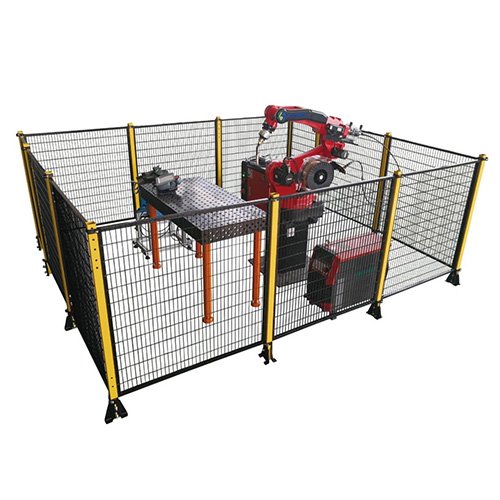
I. Training Device Structure and Operation
An aluminum alloy rail-mounted training platform is equipped with workstations such as a large workpiece discharge device, a servo-assisted handling robot, simulated punching machine processing, small workpiece feeding and assembly, automatic conveying and sorting, 6-DOF industrial robot handling, and intelligent storage and warehousing, forming a typical mechatronic mechanical platform. The electrical control system utilizes RS485 serial communication for distributed control, thus forming an automated processing and assembly line, authentically demonstrating the flexible processing of an automated production line.
The structure and functions of each workstation are as follows:
⑴ Feeding Station
The feeding station primarily consists of a hopper and trough, a pusher cylinder, a material table, and corresponding sensors and solenoid valves, as shown in Figure 1.
The operation of this station is as follows: After system startup, the pusher cylinder extends, pushing the workpiece from the bottom layer of the trough to the workpiece grabbing position on the material table. Once the workpiece arrival sensor detects the workpiece’s arrival, the pusher cylinder retracts. The handling station’s robot extends, grabs the workpiece, and transports it to the processing station. (2) Processing Station
The processing station primarily consists of a material table, a clamping robot, a material table extension/retraction cylinder, a processing (stamping) cylinder, and corresponding sensors and solenoid valves.
This station’s function is to complete a stamping process on a workpiece. The process flow is as follows:
The transfer station robot transports the workpiece to the material table → the mechanical fingers clamp the workpiece → the material table returns to the processing area below the stamping cylinder → the stamping cylinder extends downward to stamp the workpiece → after stamping is complete, it retracts upward → the stamping cylinder retracts into position → the material table re-extends → once in position, the mechanical fingers release → the transfer station robot extends, clamps the workpiece, and transports it to the assembly station.
(3) Assembly Station
The assembly station primarily consists of a feeding unit, a suction cup assembly unit, a material unloading table, and corresponding sensors and solenoid valves.
This station’s function is to complete the assembly process, namely, inserting small cylindrical workpieces (black or white) into a larger workpiece. When the robot at the handling station delivers a workpiece to the material table at the assembly station, the pusher cylinder extends, causing the small cylindrical workpiece at the bottom of the hopper to drop onto the rotating feed table. The suction-cup assembly mechanism then extends its suction cup, grabs the small cylindrical workpiece, raises its gripper, extends its arm, lowers its gripper, and releases its gripper, smoothly placing the small cylindrical workpiece into the larger workpiece. The robot at the handling station then extends, grabs the workpiece, and transports it to the material disassembly station.
⑷ Sorting Station
The sorting station primarily consists of a conveyor belt, a frequency converter, a three-phase motor, a pusher cylinder, a solenoid valve, a photoelectric positioning sensor, and a fiber optic sensor that distinguishes between black and white.
This station’s function is to sort assembled workpieces delivered from the assembly station. When a workpiece is delivered by the handling station and placed on the conveyor belt and detected by the photoelectric sensor at the inlet, the inverter is activated, and the workpiece begins to be fed into the sorting area. If the workpiece entering the sorting area is metal, the inductive sensor detecting metal serves as the activation signal for the push cylinder in slot 1, pushing the black material into slot 1. If the workpiece entering the sorting area is white, the fiber optic sensor detecting white material activates the push cylinder in slot 2, pushing the white material into slot 2. If the workpiece entering the sorting area is black, the fiber optic sensor detecting black material activates the push cylinder in slot 3, pushing the black material into slot 3. This completes the processing of the automatic production line.
⑸Servo Conveyor Mechanism
The servo conveyor mechanism primarily consists of a servo motor, servo motor driver, synchronous belt linear guide, four-degree-of-freedom handling robot, solenoid valve, and origin position switch. This station’s function is to transport workpieces to the various workstations. The system consists of a four-degree-of-freedom gripping robot unit and a linear position precision control unit. After powering on, the system first performs a home position operation. Upon reaching the home position, if the system is activated and the sensor on the material table at the feeding station detects a workpiece, the robot arm is initially raised into position, the gripper extends, and the gripper clamps. Once the gripper is fully clamped, the gripper begins to retract. Once the robot arm is fully lowered, the stepper motor activates and pulses the programmed pulses to the processing station. Once the processing station is in position, the robot arm is raised, the gripper extends, and the robot arm descends. Once the workpiece is placed on the processing station’s material table, the gripper releases. Once fully released, the robot arm retracts. After processing at the processing station, the workpiece is delivered to the assembly and sorting stations, completing the entire automated production line. (6) 6-DOF Industrial Robot Handling
It consists of a 6-DOF industrial robot body (RV-2F-1D-S11), an industrial robot driver (CR751-D), gripper input and output cables, an I/O communication module, a control cable, a teaching pendant, sensors for the clamping robot, and a solenoid valve. The six-axis robot handles workpieces that have passed the inspection and sorting unit and transports them to the intelligent warehouse unit for storage.
(7) Intelligent Stereoscopic Warehouse
The stereoscopic warehouse device is a four-story, sixteen-slot warehouse, mainly consisting of three parts: mechanical components, electrical control components, and host computer configuration. It features three-dimensional motion control (X and Z axes for bin positioning, and the Y axis for material loading and unloading).
The mechanical components are a removable modular structure, consisting of a base plate (made of industrial modular aluminum profiles), a storage unit (all-aluminum), a stacking arm (all-aluminum), a worm gear drive, a ball screw, a guide bar, special-shaped aluminum profiles, a cylinder, fingers, and button gussets.
The electrical components include a Siemens PLC (CPU226 DC/DC/DC, with other common PLCs optional), a stepper motor, a stepper motor driver, a single-phase leakage protector, fuses, a switching power supply, relays, inductive proximity switches, micro photoelectric switches, limit switches, buttons, an engineering drag chain, and an integrated cable wiring system.
The touchscreen configuration and monitoring system uses an MCGSTPC7062 touchscreen. Various function settings and selections can be made on the host computer, and the warehouse status can be monitored and controlled in real time. II. System Control Plan
Based on the aforementioned process flow of the mechanical platform, a distributed control system is implemented using RS-485 serial communication. A PLC interconnection network using the RS-485 bus is employed.
A touchscreen human-machine interface is employed, and each communication network has different configurations depending on the selected mainstream PLC manufacturer, as described below: Control Plan for the PLC Interconnection Network Using the RS-485 Bus.
The goal of this control plan is to enable students to master RS-485 communication technology and PLC interconnection technology using broadcasting to exchange information between PLCs through practical training. As a fundamental PLC communication network technology, and given the widespread use of PLC interconnection networks using the RS-485 bus in small distributed control systems, mastering this skill is essential for higher vocational students.
This equipment is configured with Siemens S7-200 series and Mitsubishi FX2N series PLCs, but users can also choose controller systems from other manufacturers. 1) Siemens S7-200 Series
This solution uses the PPI (Point-to-Point Interface) protocol for communication, with a touch screen (TPC7062) and a transfer station PLC (S7-226) serving as the intelligent warehouse station control system.
2) Mitsubishi FX2N Series:
This solution utilizes the FX2N’s N:N communication network. Each workstation is equipped with an FX2N-485-BD communication board, with the transfer station PLC (FX2N-48MT) serving as the master station and the remaining stations serving as slaves. The touch screen is connected to the master station’s programming port, and the sorting station’s FR-D700 inverter is connected to the network as slave #5. A positioning module for the servo controller is also installed. The PLC models for each station are listed in the configuration list. III. Features of This Equipment:
1. It organically integrates mechanical technology (including pneumatics), sensor technology, AC motor variable frequency speed regulation and stepper motor drive control, servo motor control technology, industrial robot control technology, touch screen technology, PLC control, and communication network technology, reflecting the characteristics of modern manufacturing production processes.
2. The overall structure adopts an open and detachable design, allowing for easy module replacement. Module content is determined based on the principle of combining productive functions with integrated learning capabilities, allowing for convenient selection of required modules during teaching or competitions. 3. For teaching purposes, activities can be planned based on a work-process-oriented, work-learning-integrated model to complete the following tasks:
1) Pneumatic System Installation and Commissioning Projects:
Using the equipment’s configured pneumatic actuators, such as single-rod cylinders, single-rod double-rod cylinders, and rotary cylinders, and pneumatic control components, such as single-control solenoid directional valves, double-control solenoid directional valves, and magnetic switches, the following pneumatic technology tasks can be completed:
Installation of pneumatic directional control circuits; Installation of pneumatic speed control circuits; Installation of swing control circuits; Installation of pneumatic sequence control circuits; Installation of pneumatic manipulators; and installation and commissioning of pneumatic systems.
2) Electrical Control Circuit Installation and PLC Programming Projects:
Using the equipment’s configured PLC modules, AC motor inverter modules, servo motor control modules, stepper motor drive modules, and sensors, the following PLC tasks can be completed. Applied Technology Tasks:
Connection and control program development for motor control circuits; connection and control program development for motor speed control circuits; connection and control program development for stepper motor control circuits; connection and control program development for servo motor control circuits; pneumatic direction control program development; pneumatic sequential motion control program development; pneumatic manipulator control program development; belt conveyor control program development; mechatronic equipment control program development; automatic production line control program development.
Industrial robot control: Control program development for multi-speed range manipulator operation, starting and braking speed change training, multi-point positioning control, robot origin and reset, single-step and continuous robot control, multi-resolution and pulse training, and network IO monitoring of robot operating status. 3) PLC communication network installation, programming, and debugging:
4) Electromechanical Equipment Installation and Debugging Project
This device uses the mechatronic equipment components, PLC modules, inverter modules, command switches, sensors, etc., to complete the following electromechanical equipment installation and mechatronic technology tasks:
Adjusting transmission coaxiality; Installing and adjusting belt conveyors; Installing and debugging handling manipulators; Installing and debugging object sorting equipment; Installing and debugging feeding equipment; Installing and debugging automatic production line equipment.
4. This equipment is used in assessments or skills competitions to assess the following professional abilities:
Assembling and adjusting mechanical components; Installing and debugging electromechanical equipment; Installing and debugging circuits; Installing and debugging pneumatic systems; Writing control programs for mechatronic equipment; Installing and debugging automatic control systems. PLC network installation, programming, and debugging abilities are also assessed. The training and assessment device’s master station PLC module’s I/O terminals, the inverter’s wiring terminals, and the terminals connecting various common modules to the PLC are all connected to safety sockets, using wires with safety plugs for circuit connections. The circuits for the command switches, photoelectric switches, sensors, and indicator elements are connected via terminal blocks. This combination of pluggable wiring and terminal block connections ensures the training, formation, and consolidation of students’ basic skills while ensuring fast, safe, and reliable circuit connections.