- Automobile training equipment series
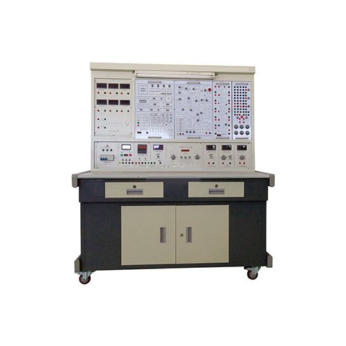
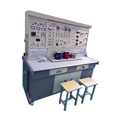
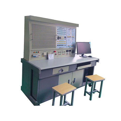
- Electrical and electronic teaching equipment
- Elevator training series
- Fitter training equipment
- Fluid mechanics experimental equipment
- Hydraulic and pneumatic test bench
- Mechanical teaching equipment
- Robotic automation and mechatronics series
- Welding training equipment

Curriculum Objectives:
Understanding the basic theory of industrial electronics circuits.
Design and implementation of the ability training for thyristor and transistor.
Ability to research and develop the thyristor and transistor.
Familiar with the applications of the high efficiency industrial electronics circuits,
Curriculum Outline:
Design and implementation of UJT and PUT thyristor circuits
Design and implementation of SCR, TRIAC, and DIAC thyristor circuits
Design and implementation of SCS, GTO, SBS, and SSR thyristor circuits
Design and implementation of MOSFET, BJT, and IGBT transistor circuits
Design and implementation of temperature sensors and optical elements circuits
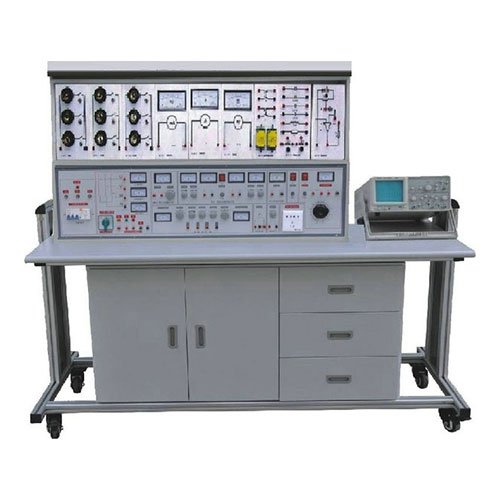
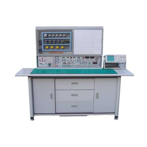
Specification:
The Industrial Electronics Circuits Trainer should consist of following nine modules with Function
Generator and DC Power Supply:
Module-1: UJT and PUT Circuits:
Experiment 1: UJT Volt-ampere
Characteristic Curve Measurement
Experiment 2: UJT Relaxation Oscillator
Experiment 3: UJT Equivalent Circuit
Experiment 4: PUT Volt-ampere
Characteristic Curve Measurement
Experiment 5: PUT Relaxation Oscillator
Module-2: SCR and GTO Circuits:
Experiment 1: SCR Characteristic
Measurement
Experiment 2: SCR Phase Angle
Controlled Circuit
Experiment 3: Zener and SCR Circuit
Experiment 4: GTO Characteristic Circuit
Experiment 5: GTO Oscillation Circuit
Module-3: DIAC and TRIAC Circuits:
Experiment 1: Zener Breakdown
Characteristic Measurement
Experiment 2: DIAC Characteristic
Measurement
Experiment 3: DIAC and TRIAC Circuit
Experiment 4: Zener and TRIAC Circuit
Experiment 5: PUT and TRIAC Circuit
Module-4: SCS and SSR Circuits:
Experiment 1: SCS Characteristic
Measurement
Experiment 2: SCS Equivalent Circuit
Experiment 3: SCS and SCR Circuit
Experiment 4: SSR DC Output Circuit
Experiment 5: SSR AC Output Circuit
Module-5: SBS Circuits and
Temperature Sensors:
Experiment I: SBS Characteristic
Measurement
Experiment 2: SBS and TRIAC Circuit
Experiment 3: Temperature Sensor
Using SCR and LM335
Experiment 4: Temperature Sensor
Using SCR and TC620
Module-6: Optical Elements and
Application Circuits:
Experiment 1: Photoresistor Circuit
Experiment 2: Photo Interrupter/Photo
Coupler Circuit
Experiment 3: Photodiode Circuit
Experiment 4: Phototransistor Circuit
Module-7: MOSFET and Application
Circuits:
Experiment 1: MOSFET Characteristic
Measurement
Experiment 2: MOSFET Regulator
Experiment 3: MOSFET Full Bridge
Circuit
Experiment 4: MOSFET PWM Controlled
Circuit
Experiment 5: MOSFET and PUT Circuit
Module-8: BJT and IGBT Application
Circuits:
Experiment 1: BJT Characteristic
Measurement
Experiment 2: BJT Full Bridge Circuit
Experiment 3: BJT PWM Controlled
Circuit
Experiment 4: IGBT Characteristic
Measurement
Experiment 5: IGBT PWM Controlled
Circuit
Module-9: SCR/SCS/DIAC/TRIAC
Application Circuits:
Experiment 1: SCR Application Circuit
Experiment 2: CdS and SCR Application
Circuit
Experiment 3: DIAC and TRIAC
Application Circuit
Experiment 4: SCS and SCR Application
Circuit
Function Generator and DC Power
Supply:
Waveforms: Sine, Triangle Square, TTI,
Pulse
Amplitude: >10Vpp
Impedance: 50ohm 10 percent
Duty Control: 30 percent-60 percent
Display: 6 Digit LED display
Frequency Range: 10HZ to 100 kHz (4
Ranges)
Range: 100HZ to 1 MHz (4 Ranges)
Constant Voltage Output: 5V, ±12V
Variable Voltage Output: 0V~15V
Power source: 220 to 230V AC, 50HZ, 1
Phase