- Automobile training equipment series
- Electrical and electronic teaching equipment
- Elevator training series
- Fitter training equipment
- Fluid mechanics experimental equipment
- Hydraulic and pneumatic test bench
- Mechanical teaching equipment
- Robotic automation and mechatronics series
- Welding training equipment

I. Overview:
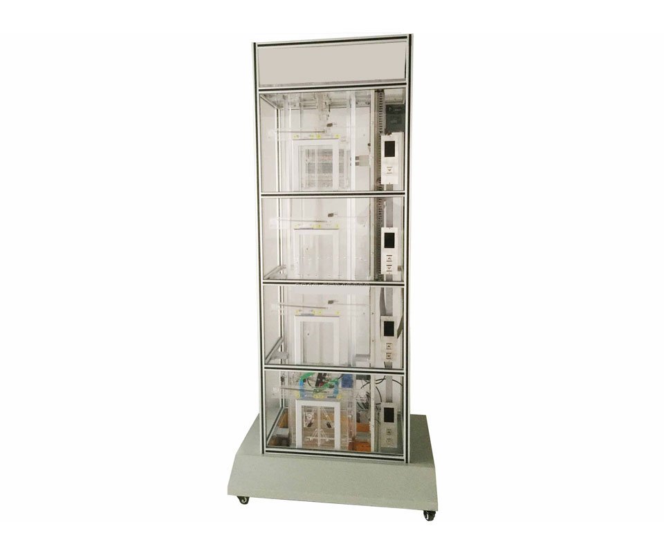
This transparent simulated teaching elevator is designed to facilitate experimental demonstrations in elevator and industrial automation courses at universities, technical schools, vocational schools, employment training centers, elevator maintenance and property management departments, and other institutions. This allows more people to better understand and use elevators, cultivate more elevator professionals, and meet the needs of the elevator industry. Our company has meticulously designed this model after in-depth research.
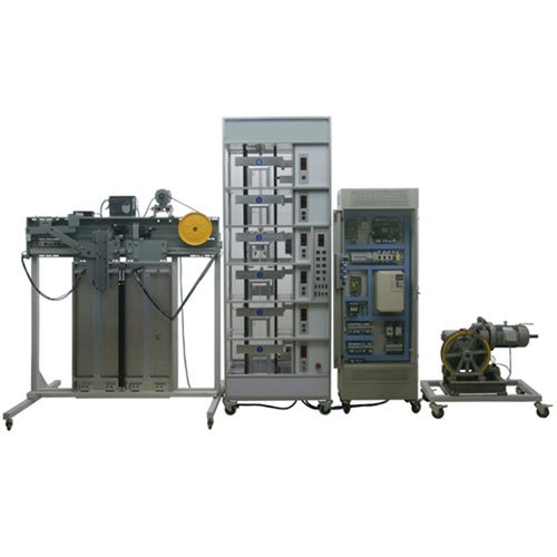
This elevator is based on the most common lift structure and is constructed of transparent organic materials. Its structure is identical to that of an actual elevator, and it possesses nearly all of its functions. To facilitate teaching, most components are constructed of transparent organic materials, making the internal structure clearly visible. Furthermore, the elevator’s operation and every movement are clearly visible, allowing for repeated hands-on practice. This allows students to intuitively and thoroughly understand and grasp the elevator’s structure and operating principles, achieving twice the result with half the effort. This model addresses the practical issues of previous elevator teaching methods, such as purely theoretical teaching methods or visits to actual elevators, which can lead to unsafe conditions and a lack of comprehensive understanding of the internal structure and operation.
The elevator’s electrical control system utilizes a Mitsubishi programmable logic controller (PLC) for intelligent logic control and a Panasonic VF100 AC variable-frequency drive. Its hardware components and functions are identical to those of an actual elevator. It features automatic leveling, automatic door opening and closing, forward response to elevator calls from inside and outside the car, direct travel, safe operation protection, emergency stop, slow ascent and descent, lighting, and a fan. It offers reliable performance, smooth operation, simple operation, low energy consumption, and ease of instruction. II. Basic Elevator Structure
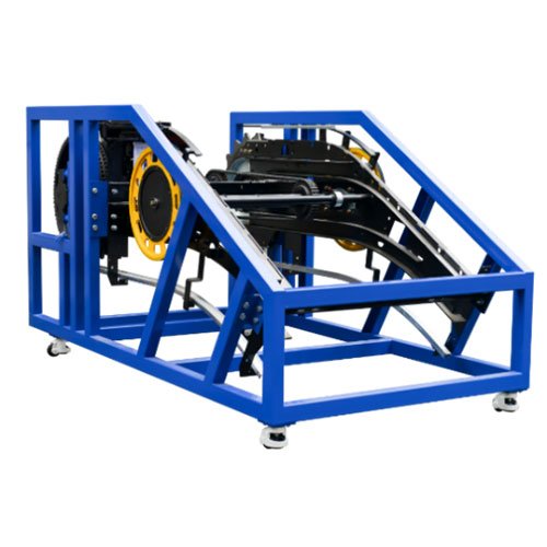
1. Machine Room: Includes the traction reducer, traction motor, brake, traction sheave, and rotary encoder;
2. Control Cabinet: Includes the main power supply, control power supply, Mitsubishi PLC, inverter, terminal block, and other equipment;
3. Hoistway: Includes the guide rails, counterweight, buffer, speed limiter wire rope tensioner, limit switch, leveling sensor, and accompanying cable;
4. Landing Door: Includes the landing door, call button compartment, and floor display;
5. Car: Includes the car, car door and touch panel, speed limiter switch, speed limiter lever, safety clamp, guide shoe, door mechanism, open and close position switches, leveling sensor, car lighting, and fan.
III. Basic Functions of Elevator Mechanical Devices
A. Overspeed Safety Protection System
When an elevator accident occurs, the car may overspeed or descend at high speed (e.g., due to wire rope breakage, detachment of the car top pulley, malfunction of the traction machine worm gear, or excessive motor speed). At this point, the speed governor activates the emergency brake, driving the safety clamps through the safety cable and linkage mechanism, locking the car on the guide rails and preventing it from falling.
B. Spring Buffers for Car and Counterweight
The buffers are safety devices for elevator extreme positions. When an elevator malfunction causes the car or counterweight to bottom out or top out (limit switch protection fails), the car or counterweight impacts the spring buffers, which absorb the energy from the elevator, safely slowing the car or counterweight to a stop.
C. Door Safety Touch Plate Protection Device
A movable safety touch plate is installed on the edge of the car door. When the door is closing and the safety touch plate contacts a passenger or obstacle, a linkage connected to the safety touch plate triggers a microswitch on the car door, causing the door to reopen, preventing an accident. D. Upper and Lower Limit Switches:
These switches are installed at the upper and lower ends of the elevator shaft, within the upper and lower limit switches. Their purpose is to protect the elevator car from exceeding these limits. If the upper or lower limit is exceeded, the motor automatically stops and ceases operation. Unlike the upper and lower limit switches, these switches do not lose power.
E. Automatic Landing Door Closing Device:
The elevator landing doors are opened and closed by door blades installed on the car doors. Each landing door is equipped with a door lock. When the landing door is closed, the mechanical lock hook of the door lock engages, allowing the elevator to start.
F. Landing Door Interlock Switch:
When all landing doors are closed, the elevator can ascend or descend. If even one landing door is open, the elevator cannot operate.
G. Terminal Limit Switch Safety Protection System: Terminal limit switches are installed at the top and bottom floors of the elevator shaft. If the elevator loses control due to a malfunction and the car hits the top or bottom, the terminal limit switches activate, generating an alarm signal and disconnecting the control circuit, causing the car to stop. IV. Main Technical Parameters
Dimensions: Length * Width * Height = 900 * 600 * 2530 mm (2)
Net Weight: 135 * 2 kg
Load Capacity: 5 kg
Inverter: Panasonic VF200
Input Voltage: 220V
Input Frequency: 50Hz
Rated Current: 2.5A
Power: 0.4 kW
Traction Motor Reduction Ratio: 1:15
Module: 1.5 (Worm Gear Reducer)
Traction Motor Model: YS-5634W
Voltage: 3 * 220V
Power: 0.18 kW
Speed: 1400 rpm
Control Method: PLC (Mitsubishi FX3U-64MR)
Speed Regulation: AC Variable Frequency Drive
Structure: Six-Decker, Six-Station Elevator
Leveling Mechanism: Rotary Encoder/Permanent Magnet Sensor
V. Electrical Control
1. Basic Functions
1) Automatic Leveling
2) Automatic Door Opening and Closing, Manual Pre-Opening and Closing
3) Forward response to elevator call information
4) Rope break protection, speed limit protection, buffer protection, overload protection, etc.
5) Upper and lower limit protection, car door safety touch panel protection, upper and lower terminal limit switch protection
6) Landing door interlock protection
7) Automatic/manual, direct-drive operation
8) Slow up and slow down operation
9) Lighting, fan, emergency stop, etc.
2. Special Features
1) Leveling settings and program learning function
2) Continuous docking automatic test demonstration
3) PLC connection and program upload and download
4) PLC monitoring and debugging and parameter setting
5) VFD parameter setting and debugging
6) Overspeed fault, speed limiter safety clamp demonstration
7) Door opening and closing time protection, leveling height setting
8) VFD preset speed control deceleration-slow-stop
VI. Practical Training Projects
1. Sensor Detection
2. Basic VFD Operation
3. Timer Instructions
4. Mathematical Operation Instructions
5. High-Speed Counter
6. Automatic Car Door Opening and Closing Control
7. Elevator Run Call Indicator Driver
8. Floor Display
9. Hall Door Safety Control
10. Elevator Terminal Switch Protection
11. Elevator Lift and Lower Deceleration Control
12. Positioning with Photoelectric Encoders