- Automobile training equipment series
- Electrical and electronic teaching equipment
- Elevator training series
- Fitter training equipment
- Fluid mechanics experimental equipment
- Hydraulic and pneumatic test bench
- Mechanical teaching equipment
- Robotic automation and mechatronics series
- Welding training equipment

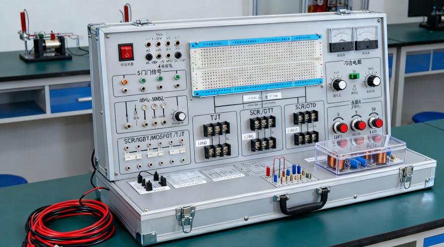
I. System Composition of the Digital Circuit Experiment Box:
1. Power Supply: AC Input: 220V±10%, 50Hz; DC Output: ±12V/0.3A, 5V/2A
2. Two sets of manual single-pulse circuits: Each set can simultaneously output two positive and two negative pulses, with pulse amplitude at TTL level.
3. Seven fixed-frequency pulse sources, all outputting at TTL level: 1Hz, 10Hz, 100Hz, 1KHz, 10KHz, 100KHz, 1MHz;
4. Timing pulse generation circuit and start/stop control circuit. It can generate four pulse signals, with the pulse period matching the input clock signal, and the four pulses differing from each other by one input clock cycle.
5. Six-digit high-precision digital frequency meter, measurement range: 0-9.9999MHz, error <1Hz
6. Sixteen-bit logic level input switch: can input low level ‘0’ and high level ‘1’ (positive logic). 7. Sixteen-bit logic level indicator: Red indicates high level ‘1’, green indicates low level ‘0’.
8. Digital tube display: A six-bit BCD code decoding and display circuit composed of seven-segment LED digital tubes. For use in experiments such as digital clocks and calendars.
9. Two variable potentiometers, with resistance values of 22K and 100K respectively.
10. Open experimental area for extended experiments and course design.
(1) Provides eight locking sockets: two 40-pin sockets, two 20-pin sockets, and four 16-pin sockets, which can accommodate ICs with pins ranging from 8 to 40.
(2) Two breadboards made in Taiwan, which can be used to connect resistors, capacitors, Zener diodes, diodes, transistors, and other components. 11. EDA Expansion Area: The standard configuration is the Lattice 1032 experimental board. Optional boards, such as the Lattice 4256, Altera EPM7128s, Altera EP1K30, Altera EP1K100, and Xinlix 95108, can also be selected according to school requirements.
II. Experimental Items in the Digital Circuit Experiment Box:
(I) Recommended Digital Circuit Experiments:
1. Parameter Testing and Use of TTL Integrated Logic Gates
2. Testing of CMOS Integrated Logic Gates
3. Logic Function Experiments of Gate Circuits
4. Testing of Commonly Used Combinational Logic Devices
5. Data Selectors and Their Applications
6. Blood Type Relationship Detection Circuit and Voting Circuit
7. Function and Testing of RS Flip-Flops
8. Logic Function and Main Parameter Testing of JK Flip-Flops