- Automobile training equipment series
- Electrical and electronic teaching equipment
- Elevator training series
- Fitter training equipment
- Fluid mechanics experimental equipment
- Hydraulic and pneumatic test bench
- Mechanical teaching equipment
- Robotic automation and mechatronics series
- Welding training equipment

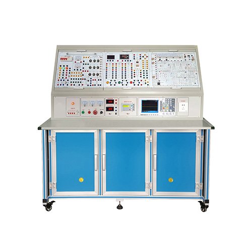
This electrical training device is a new generation of multi-functional equipment designed based on the actual situation of primary and intermediate electrician training and assessment. It integrates electrical theory teaching, practical training, and assessment. The device features timed and error recording assessment functions, and is equipped with various safety measures. It can complete the practical projects of electric drive control and lighting circuits in primary and intermediate electrician assessments. It meets the requirements of electrician on-the-job training, practical operation, and assessment. It is an ideal teaching device for electrician and electric drive practical training and assessment in vocational schools, technical schools, and labor vocational skills assessment departments.
I. Product Features
1. Safety Performance
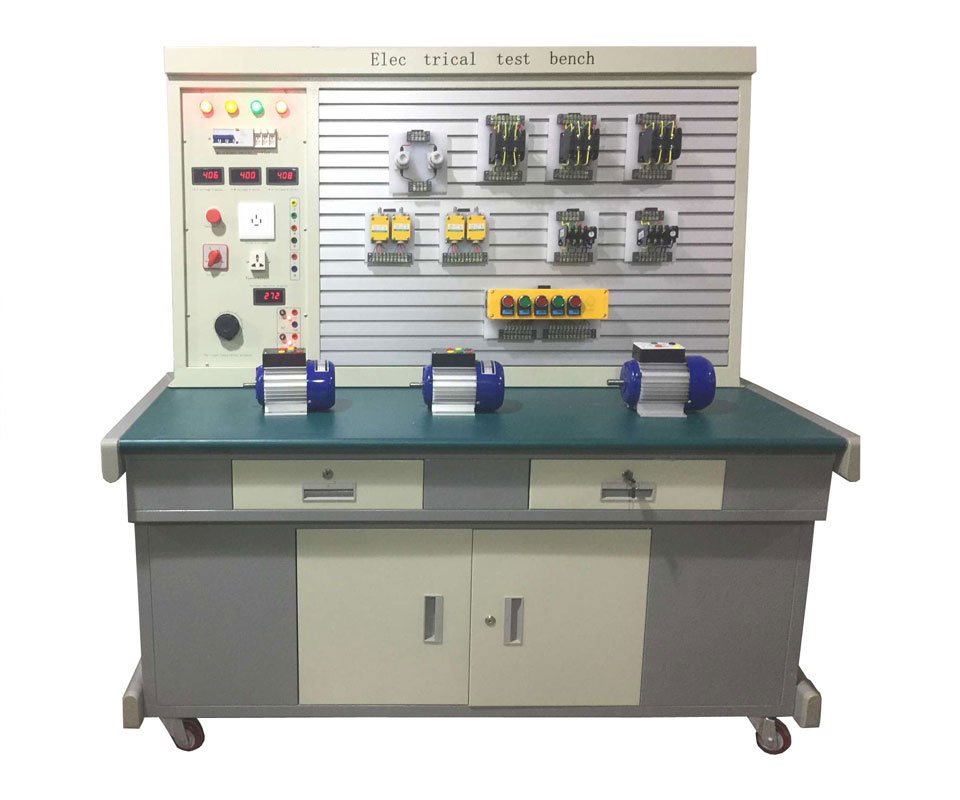
The device is equipped with current-type and voltage-type leakage protection devices to ensure personal safety, suitable for the special requirements of student operation. It also has overcurrent or short-circuit protection devices to ensure equipment safety. The device is powered by a three-phase five-wire power supply, controlled by a contactor via start/stop buttons, and includes a three-phase voltmeter. The system is equipped with a current-type leakage current protector. If leakage occurs on the control panel and the leakage current exceeds a certain value, the power supply will be cut off. It also has a voltage-type leakage current protector. If leakage occurs in the main power output or during wiring in the experiment, an alarm will sound and the contactor inside the device will trip, cutting off the power supply to ensure personal safety. An overcurrent protection device is also provided. If there is a short circuit at the output or the load is too large and the current exceeds the set value, the system will alarm and cut off the main power supply to ensure equipment safety.
2. Rational Structure: The equipment uses a standard distribution cabinet as the main cabinet, utilizing the double-sided space of the cabinet to scientifically arrange electrical appliances and supporting experimental equipment. The cabinet is rationally designed, convenient to operate, and multi-functional. All electrical component contacts are connected to terminal blocks, allowing students to simply connect wires for experiments, extending the lifespan of electrical components and reducing material waste.
3. Aesthetic Appearance: The device has a rational layout and an aesthetically pleasing appearance. The panel diagram is clear and intuitive. The wiring is neat and tidy, reducing potential points of failure and improving reliability. The device adopts a double-layer matte textured powder-coated iron structure; the structure is sturdy and aesthetically pleasing. The product boasts a beautiful and elegant appearance, along with advanced structure and craftsmanship, making it pleasing to the eye.
II. Experimental Projects
Experiment 1: Touch Switch Control Circuit for Incandescent Lamp
Experiment 2: Incandescent Lamp Control Circuit
Experiment 3: Human Body Induction Switch Control Circuit for Staircase Incandescent Lamp
Experiment 4: Fluorescent Lamp Control Circuit
Experiment 5: Direct Installation Circuit for Single-Phase Electricity Meter
Experiment 6: Indirect Installation Circuit for Single-Phase Electricity Meter
Experiment 7: Single-Phase Motor Start/Stop Control Circuit
Experiment 8: Wiring Diagram for Current Transformer and Ammeter
Experiment 9: Voltmeter and Ammeter Installation Circuit
Experiment 10: Direct Installation Circuit for Three-Phase Four-Wire Active Energy Meter
Experiment 11: Indirect Installation Circuit for Three-Phase Four-Wire Active Energy Meter
Experiment 12: Direct Installation Circuit for Three-Phase Four-Wire Reactive Energy Meter
Experiment 13: Indirect Installation Circuit for Three-Phase Reactive Energy Meter
Experiment 14: Wiring Circuit for Measuring Three-Phase Voltage with Universal Transfer Switch and Voltmeter
Experiment 15: Asynchronous Motor Jogging Control Circuit
Experiment 16: Asynchronous Motor Self-Locking Control Circuit
Experiment 17: Overload Protection Self-Locking Control Circuit
Experiment 18: Asynchronous Motor One-Way Jogging Start Control Circuit
Experiment 19: Asynchronous Motor Two-Location Control Circuit
Experiment 20: Asynchronous Motor Interlocking Forward and Reverse Control Circuit
Experiment 21: Forward and Reverse Jogging and Starting Control Circuit
Experiment 22: Double Interlocking Forward and Reverse Control Circuit
Experiment 23: Automatic Reciprocating Control Circuit
Experiment 24: Automatic Reciprocating Control Circuit with Jogging
Experiment 25: Contactor Control Star-Delta Control Circuit
Experiment 26: Time Relay Switching Y/Δ Starting Control Circuit
Experiment 27: Series Resistor Voltage Reduction Starting Control Circuit
Experiment 28: Asynchronous Motor Reverse Braking Control Circuit
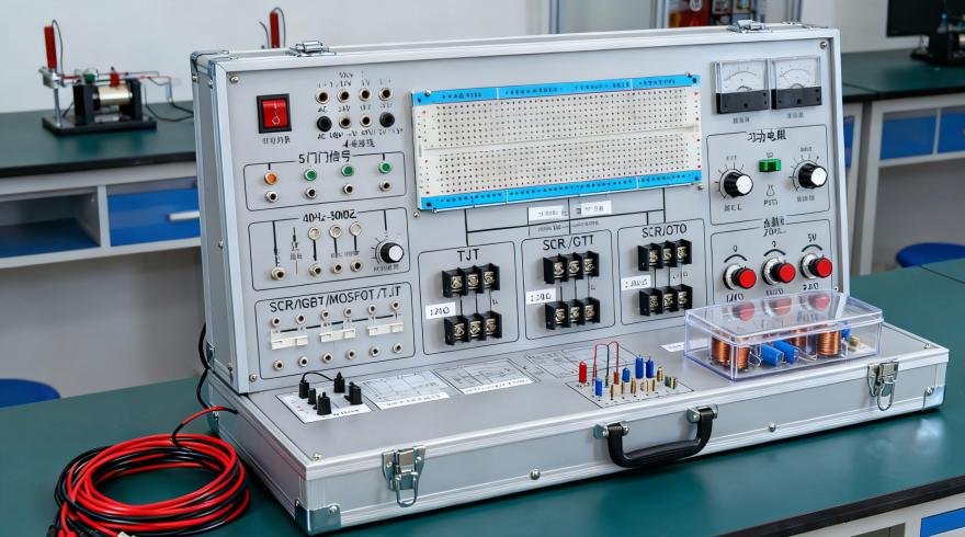
Experiment 29: Half-Wave Rectifier Energy Consumption Braking Control Circuit
Experiment 30: Full-Wave Rectifier Energy Consumption Braking Control Circuit
Experiment 31-39: Dual-Speed Motor Switching Operation Control
Experiment 32: Manual Sequential Starting Control
Experiment 33: Automatic Sequential Starting Control
Experiment 34: Electric Hoist Electrical Control Circuit
III. Technical Parameters
1. Input Power: AC380V±5% (Three-phase five-wire) 50±1Hz
2. Rated Current: 5A
3. Relative Temperature: -5℃~40℃ Relative humidity: <75% (25℃)
4. Dimensions: 750×550×1800mm, cabinet type, double-sided
5. Equipment weight: 200kg