- Automobile training equipment series
- Electrical and electronic teaching equipment
- Elevator training series
- Fitter training equipment
- Fluid mechanics experimental equipment
- Hydraulic and pneumatic test bench
- Mechanical teaching equipment
- Robotic automation and mechatronics series
- Welding training equipment

I. Overview
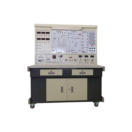
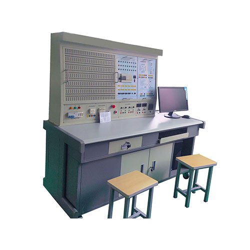
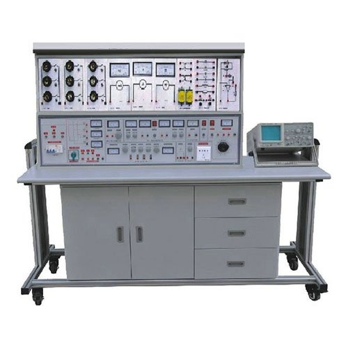
The “Electrical Machine and Electrical Technology Experimental Device” is a novel, comprehensive experimental device designed by our company. It integrates the requirements of current experimental syllabi for courses such as “Electrical Machines,” “Electrical Machines and Drives,” “Control Micromotors,” “Motor Control,” “Relay Contact Control,” “Programmable Logic Controller Technology,” and “Factory Electrical Control” in higher education institutions. It is particularly suitable for upgrading and renovating existing electrical machine and electrical technology experimental equipment in higher education institutions. It also provides ideal experimental equipment for the construction or expansion of laboratories in secondary vocational schools and vocational colleges, enabling the rapid introduction of experimental courses. It provides excellent experimental conditions for teachers or graduate students to develop new experiments or conduct scientific research.
II. Features
1. High Comprehensiveness: This device integrates all experimental items for electrical machine and electrical technology courses in various domestic colleges and universities.
2. High Adaptability: It can meet the experimental teaching needs of corresponding courses in various schools. The depth and breadth of experiments can be flexibly adjusted as needed, and popularization and advancement can be organically combined according to the teaching progress. The device adopts a modular structure, making replacement convenient. If it is necessary to expand functions or develop new experiments, only additional components are needed; it will never become obsolete.
3. **Comprehensive Setup:** The system is fully equipped with instruments, dedicated power supplies, motors, and other experimental components, as well as dedicated connecting wires. The performance and specifications of the components are closely tailored to the needs of the experiments.
4. **Highly Intuitive:** Each experimental component uses a partitioned structure, with clear diagrams and lines on the panel. Each component has a clearly defined function, facilitating operation and maintenance.
5. **Scientific Approach:** The device occupies a small area, saving on laboratory space and infrastructure investment. The accompanying small motors are specially designed to simulate the characteristics and parameters of small and medium-sized motors. These motors are energy-efficient, resulting in low noise levels and a neat, aesthetically pleasing experimental environment. The electrical control experiments are rich in content and rationally designed, deepening theoretical knowledge and laying a solid foundation for students’ future careers. The measuring instruments combine pointer-type (with over-range alarms, etc.), analog-digital dual-display, digital, intelligent, and human-computer interaction technologies, closely configured to meet the needs of teaching experiments, modernizing the device’s measurement methods. A timer/alarm recorder provides a unified standard for assessing students’ experimental skills.
6. The control panel features strong openness and power supply isolation (floating ground design), and is equipped with internal and external voltage-type leakage protection devices and current-type leakage protection devices to ensure operator safety. Each power output has monitoring and short-circuit protection functions, making it easy to use. All measuring instruments have protection functions. The entire system is meticulously designed, and with reliable component quality and manufacturing processes as a guarantee, the product performs excellently. All of these factors create conditions for open-ended experiments, which is conducive to improving students’ ability to analyze and solve problems.
III. Technical Performance
1. Input Power: Three-phase four-wire (or three-phase five-wire) ~380V±10%50Hz
2. Working Environment: Temperature -10℃~+40℃, relative humidity <85% (25℃), altitude <4000m
3. Device Capacity: <1.5KVA
4. Weight: 480Kg
5. Dimensions: 1700×720×163mm
IV. Basic Equipment of the Device
1. Power Control Panel (iron powder-coated structure, aluminum panel)
(1) AC Power Supply Provides three-phase 0~450V adjustable AC power supply, and can also obtain single-phase 0~250V adjustable power supply (equipped with a three-phase coaxial linkage autotransformer (specification 1.5KVA, 0~450V), which overcomes many disadvantages of the three single-phase voltage regulators using chain structure or gear structure). The adjustable AC power output is equipped with overcurrent protection technology, automatically protecting against phase-to-phase and line-to-line overcurrent and direct short circuits, overcoming the inconvenience of replacing fuses. It features three pointer-type AC voltmeters, which indicate the three-phase grid voltage and three-phase adjustable voltage via a switch.
(2) Two-way high-voltage DC power supply: Provides one set each of a 220V (0.5A) excitation power supply and a 20-230V (3A) continuously adjustable regulated armature power supply (with overvoltage, overcurrent, overheat, and short-circuit soft-cutoff automatic recovery protection functions), and includes a DC digital display voltmeter and a switch. (3) Five-System Personal Safety Protection:
A three-phase isolation transformer is provided (the three-phase power supply passes through a key switch and contactor, then to the isolation transformer, and finally to the output via a three-phase voltage regulator), isolating the output from the power grid and providing a certain degree of protection for personal safety;
A voltage-type leakage current protector 1 is provided, which can protect and cut off the power supply if there is leakage in the line before the isolation transformer;
A voltage-type leakage current protector 2 is provided, which can alarm and cut off the power supply if there is leakage in the line after the isolation transformer or in the wiring during the experiment;
A current-type leakage current protector is provided, which will cut off the power supply if there is leakage in the control panel and the leakage current exceeds a certain value. The high-voltage connection lines and sockets adopt a fully enclosed structure, ensuring safe, reliable, and shock-proof operation.
(4) Instrument Protection System:
Multiple signal sockets are provided, connected to the instruments. If the instrument exceeds its range, it can alarm and cut off the power supply, providing good protection for the instrument.
(5) Timer/Alarm Recorder (Service Manager):
Features functions such as setting time, alarming at the end of the time, cutting off the power supply, and recording the number of alarms. (6) Two stainless steel pipes are installed in the large recess on the front of the control panel for hanging instruments and experimental components. Multiple small round single-phase three-core 220V power sockets are located at the bottom of the recess for powering instruments and other components. Three-pole 220V power sockets and three-phase four-pole 380V power sockets are located on both sides of the control panel. A 220V, 40W fluorescent lamp is provided for lighting the experimental table.
2. Experimental Table
The experimental table is made of double-layered matte textured powder-coated iron. The tabletop is made of fireproof, waterproof, and wear-resistant high-density board, with a sturdy structure and a rectangular, closed design that is aesthetically pleasing. It has two large drawers and cabinet doors for storing tools, hanging items, and documents. The tabletop is used to install the power control panel and provides a spacious and comfortable work surface. The experimental table also has four casters and four fixed adjustment mechanisms for easy movement and fixation, which is beneficial for laboratory layout.
3. Stainless Steel Motor Rails, Tachogenerator, and Tachometer
Includes a tachogenerator and stainless steel rails for fixing the motor. The stainless steel guide rails have good flatness, no stress deformation, fine processing, good concentricity, and good interchangeability. They can ensure that the concentricity of the connection between motors and between the motor and the dynamometer does not exceed ±5 microns. The motor operates with low noise, and the experimental parameters are typical, which can well meet the experimental requirements.
4. Three-phase transformer group (composed of three identical single-phase transformers, primary side 220V/0.35A, secondary side 55V/1.4A)
5. DC compound-wound generator
6. DC shunt motor
7. Compound-wound DC motor
8. Three-phase squirrel-cage asynchronous motor
9. Three-phase wound-rotor asynchronous motor
10. Three-phase synchronous motor
11. Single-phase capacitor-start asynchronous motor
12. Three-phase dual-speed asynchronous motor
13.Calibrated DC dynamometer;
220V, 2.0A, 350W, 1500r/min, this unit can function as both a motor and a dynamometer. When used as a motor, it can serve as the prime mover for a generator or drive a motor to complete four-quadrant testing. When used as a dynamometer, due to its special design and 2-3 times the capacity of the motor being tested, and calibrated with precision instruments, it can effectively test the loaded output torque of the motor under test.
13. Single-phase and Three-phase Intelligent Power and Power Factor Meters: Designed with a 24-bit dedicated DSP, a 16-bit high-precision AD converter, and a high-speed MPU unit, this unit features a human-machine interface control mode via keypad and digital display. The software adopts an RTOS design approach and is equipped with PC monitoring software to enhance analytical capabilities. It can simultaneously measure the power of two single-phase phases, P1 and P2, and display the sum of the two power values (two-meter method for measuring total three-phase power) via a separate 5-digit LED display. The power measurement accuracy is 1.0 class, the power factor measurement range is 0.3-1.0, and the voltage and current ranges are 450V and 5A. It can automatically identify the load type (inductive load displays “L”, capacitive load displays “C”, pure resistance displays nothing) and store measurement data for easy reference.
14. Three-phase adjustable resistors (three sets of 90Ω×2/1.3A ceramic disc resistors)
15. Three-phase adjustable resistors (three sets of 900Ω×2/0.41A ceramic disc resistors)
16. Adjustable resistors and capacitors: Provides one set each of 90Ω×2/1.3A and 900Ω×2/0.41A ceramic disc resistors, and one each of 35μF/450V and 4μF/450V power capacitors.
17. Waveform testing and switchboard: Consists of the transformer waveform testing section, two three-pole double-throw switches, and one double-pole double-throw switch.
18. Relay Contact Control (I) Provides one circuit breaker, one filler fuse, one black fuse for protecting the control circuit, two indicator lights, one lighting light, three pushbuttons (one each of yellow, green, and red), one AC contactor, and one thermal relay. All components are mounted on the panel of the training assembly.
19. Relay Contact Control Assembly (II) Provides two AC contactors, one time relay, one 220V/26V/6.3V transformer, one rectifier bridge, one energy-dissipating braking resistor, and one pushbutton. All components are mounted on the panel of the experimental assembly.
20. Equipped with a Mitsubishi FX1N-40MR programmable controller main unit and matching Mitsubishi programming cable. Provides a +24V DC power supply required for the experiment. An overvoltage protection circuit is included to protect the main unit from damage due to excessive power supply voltage.
21. Experimental Connection Cables and Accessories
The cables utilize a highly reliable sheathed, hand-operated connection structure (eliminating any possibility of electric shock). The internal wires are made of oxygen-free copper, drawn to a fine, hair-like consistency for ultra-softness. An outer layer of nitrile polyvinyl chloride insulation provides flexibility, high voltage resistance, high strength, resistance to hardening, and good toughness. The plug uses solid copper components with beryllium-copper spring contacts for excellent contact.
V. Safety Protection System of the Apparatus
1. Three-phase four-wire (or three-phase five-wire) power input is isolated and output (floating ground design). The main power supply is controlled by a three-phase key switch, and a three-phase illuminated fuse is provided as a phase failure indicator.
2. The control panel power supply is controlled by a contactor via start and stop buttons.
3. The panel is equipped with two sets of voltage-type leakage protection devices. If leakage occurs within the control panel or at the high-voltage output, an alarm will sound and the main power supply will be cut off to ensure the safety of the experiment.
4. The control panel is equipped with a current-type leakage current protector. If leakage occurs and the leakage current exceeds a certain value, the power supply will be cut off.
5. The three-phase voltage regulator on the control panel is equipped with an overcurrent protection device on both the primary and secondary sides. If the voltage regulator short-circuits or the load is too large, and the current exceeds the set value, the system will alarm and cut off the main power supply.
6. A timer/alarm recorder (service manager) is provided to record the number of times unauthorized use occurs, providing a unified standard for assessing students’ experimental skills.
7. All power supplies and instruments have reliable protection functions.
8.The experimental connection cables are safe, reliable, and protected against electric shock.
VI. Experimental Items
(I) DC Motor Experiments
1. Introduction Experiment
2. DC Generator
3. DC Shunt Motor
4. DC Series Motor
(II) Transformer Experiments
1. Single-Phase Transformer
2. Three-Phase Transformer
3. Connection Groups and Asymmetrical Short Circuits of Three-Phase Transformers
4. Three-Phase Three-Winding Transformer
5. Parallel Operation of Single-Phase Transformers
6. Parallel Operation of Three-Phase Transformers
(III) Asynchronous Motor Experiments
1. Operating Characteristics of Three-Phase Squirrel-Cage Asynchronous Motors
2. Starting and Speed Regulation of Three-Phase Asynchronous Motors
3. Single-Phase Capacitor-Started Asynchronous Motors
4. Single-Phase Capacitor-Started Asynchronous Motors
5. Single-Phase Capacitor-Runned Asynchronous Motors
6. Dual-Speed Asynchronous Motors
7. Three-Phase Asynchronous Generators
(IV) Synchronous Motor Experiments
1. Three-Phase Synchronous Generators 1. Operating characteristics of a motor
2. Grid-connected operation of a three-phase synchronous generator
3. Three-phase synchronous motor
4. Measurement of parameters of a three-phase synchronous motor
(V) Measurement of the mechanical characteristics of a motor
1. Mechanical characteristics of a separately excited DC motor under various operating conditions
2. Mechanical characteristics of a three-phase asynchronous motor under various operating conditions
3. Plotting the M-S curve of a three-phase asynchronous motor
(VI) Experiments on controlled motors
1. Experiment on a permanent magnet DC tachogenerator
2. Experiment on a rotary encoder
3. Experiment on a torque-type synchro
4. Experiment on a controlled synchro
5. Experiment on sine and cosine rotary transformers
6. Experiment on a stepper motor
7. Experiment on a linear motor
8. Experiment on a high-voltage DC brushless motor
(VII) Experiments on relay contact control and electric drive (electrical control)
1. Three-phase asynchronous 1. Motor jogging and self-locking control circuit
2. Three-phase asynchronous motor forward and reverse rotation control circuit
3. Three-phase asynchronous motor Y-Δ reduced voltage starting control circuit
4. Three-phase asynchronous motor energy consumption braking control
5. Starting sequence control of two three-phase asynchronous motors
6. Three-phase wound asynchronous motor starting control circuit
7. Control circuit of dual-speed asynchronous motor
8. Automatic reciprocating cycle control circuit of worktable
9. Two-location control circuit
10. Electrical control circuit of C620 lathe
11. Electric hoist electrical control circuit experiment
12. Debugging and analysis of X62W milling machine simulation control circuit
13. Electrical control circuit of M7130 surface grinder
(VIII) Programmable Controller Experiment
1. Basic instruction programming practice
2. Simulation control of vending machine
3. IV Simulation of elevator control system
4. Simulation of liquid mixing device control
5. Motor control (jog control, self-locking control, forward/reverse control, star/delta start)
6. Simulation of four-section conveyor belt
7. Simulation of automatic feeding and loading system control
8. Simulation of robotic arm movement
9. Simulation of LED digital display control
10. Simulation of five-phase stepper motor control
11. Simulation of traffic light control at an intersection
12. Sequence control of assembly line
13. Simulation of water tower level control
14. Simulation of rolling mill control system
15. Simulation of mail sorting system
16. Automatic stamping system
17. Simulation of fountain control
18. Simulation of machining center control
19. Simulation of automatic washing machine
20. Simulation of electroplating system