- Automobile training equipment series
- Electrical and electronic teaching equipment
- Elevator training series
- Fitter training equipment
- Fluid mechanics experimental equipment
- Hydraulic and pneumatic test bench
- Mechanical teaching equipment
- Robotic automation and mechatronics series
- Welding training equipment

I. Significance of Developing This Product:
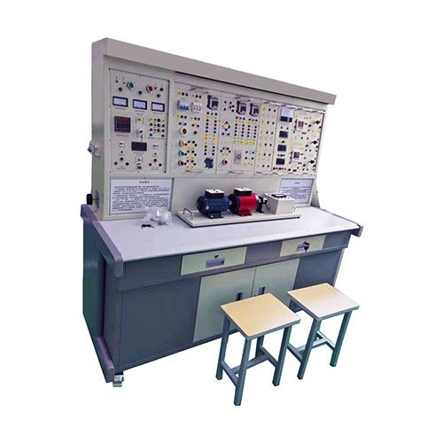
This equipment can complete the basic DC motor experiments required by the teaching syllabus. Its successful development solves the problems faced by many schools in procuring, managing, and conducting DC motor experiments due to difficulties in purchasing and managing components. This equipment organically integrates electrical engineering, electrical principles, electronic technology, electric drive control circuits, and DC motor experiments, significantly saving on laboratory space, management personnel, and funds. It greatly improves management efficiency and standardization, and significantly reduces the workload of teachers in preparing experiments. This equipment is an ideal choice for schools seeking a one-stop solution for large-scale, high-quality work.
II. Structure and Equipment:
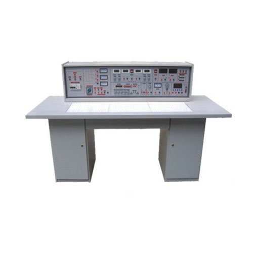
1. Experiment Tables: One table with two seats. Table dimensions: 160×70×80cm. A universal circuit board is located in the center of each table. Each table is equipped with a rubber sheet to protect the circuit board and the tabletop (if needed for placing motors, soldering, etc.). Component storage cabinets are located under the tables for storing components.
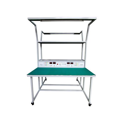
2. Experimental Platform: Based on the DB-28C general-purpose electrical and electronic laboratory equipment set, a DC motor speed control circuit, Ia and If indicators, and a 0-220V DC power supply are added. One student experimental table and one teaching control console are provided.
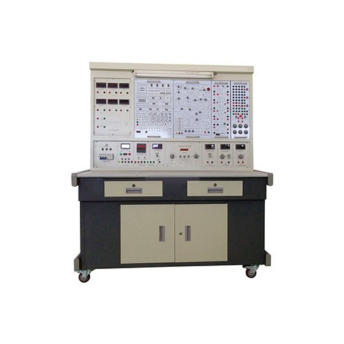
3. Teaching Control Console: One teaching control console controls the power supply of 12 student tables. A general-purpose circuit board demonstration screen, measuring 150cm × 70cm, stands on the experimental platform for explanation and demonstration. 4. Equipment: 26 three-phase 180W motors, 13 100W DC motors, 26 time relays, 78 AC contactors, 156 AC/DC meters, 13 MF-500 multimeters, 39 indicator lights, 52 limit switches, 78 control buttons, 13 forward/reverse switches, 26 transformers, 13 three-phase double-throw switches, 13 three-phase switches, 13 sets of component boxes (components already installed) containing resistors, potentiometers, inductors, mutual inductors, diodes, transistors, MOSFETs, integrated circuits, thyristors, logic level switches, logic level indicators, etc., required for the experiment; 13 sets of wire strippers, screwdrivers, needle-nose pliers, etc.
5. User-provided equipment: Oscilloscope (model not limited), transistor millivoltmeter, etc.
III. Experimental Items: (1) Electrical Engineering Experiment
1. Use of electrical measuring instruments
2. 1. Identification and Testing of Common Components
2. Irradiance Characteristics of Linear and Nonlinear Components
3. External Characteristics of Power Sources
4. Measurement of Potential and Voltage Values
5. Range Extension of Ammeters and Voltmeters
6. Verification of Kirchhoff’s Laws
7. Verification of Lenz’s Law
9. Verification of the Superposition Principle and Reciprocity Theorem
10. Verification of Thevenin’s Theorem and Norton’s Theorem
11. Equivalent Transformation of Voltage and Current Sources
12. Study of Controlled Source Characteristics
13. Experiments on First-Order Circuits
14. Transient Process of Second-Order Circuits
15. Study of the Characteristics of LC Components in DC and AC Circuits
16. Conditions for a Load to Obtain Maximum Power
17. Measurement of AC Circuit Parameters
18. Characteristics of RLC Components in Sinusoidal AC Circuits
19. Experiments on RL and RC Series Circuits
20. RLC Series Resonant Circuit
21. Connection and Power Factor Improvement of Fluorescent Lamp Circuits
22. Star and Delta Connections of Three-Phase Loads
23. Three-Phase Circuits and Power Measurement
24. Research on R-C Frequency Selection Networks
25. Research on Two-Port Networks
26. Single-Phase Transformer Experiment
27. Mutual Inductance Circuit Experiment
28. Use and Starting of Three-Phase Asynchronous Motors
29. Basic Circuit of Relay Contact Control for Three-Phase Motors
30. Y-Δ Starting Control Experiment for Three-Phase Motors
31. Sequential Control Experiment for Three-Phase Motors
32. Energy Consumption Braking Control Experiment for Three-Phase Motors
The following circuit experiments can also be completed using the components from the above 32 experiments:
33. The Simplest Circuit
34. Selection of Potential and Reference Point in a Circuit
35. Series Connection of Resistors
36. Parallel Connection of Resistors
37. Mixed Connection of Resistors
38. 39. Ohm’s Law for the Entire Circuit
40. Application and Balance Conditions of a Bridge Circuit
41. Nodal Voltage Method
42. Loop Voltage Method
43. Branch Current Method
44. Parallel RCL Circuit
45. Series Circuit
46. Transformer Structure and Working Principle
47. Kirchhoff’s First Law
48. Kirchhoff’s Second Law
49. Fluorescent Lamp Circuit Principle
50. Extending the Voltmeter Range
51. Extending the Ammeter Range
52. Transient Process of an RC Circuit
53. Transient Process of an RL Circuit
54. Series Circuit of Capacitors
55. Parallel Circuit of Capacitors
56. 57. Capacitor Charging and Discharging
58. The Role of Capacitors in AC/DC Circuits
59. The Movement of a Bar Magnet in a Coil
60. Mixed Connection of Capacitors
61. Circuits with Pure Resistance, Inductance, and Capacitance
62. Forward Connection of Magnetic Coupled Coils
63. The Working Principle of an Ohmmeter
64. Two-Pole Switch Controlled by Two Grounds
65. Observing the Hysteresis Loop with an Oscilloscope
66. Ohm’s Law for Magnetic Circuits
67. Mutual Inductance and Corresponding Terminals of Two Coils
68. Mutual Inductance Coupling
69. Methods to Improve the Power Factor
70. Measurement of Power in a Single-Phase Circuit
71. Radio Recorder Power Supply Circuit
72. Filter Circuit
73. Relationship between Resistance and Temperature: Measuring the Resistance of a Filament at Different Voltages Using the Voltmeter-Ammeter Method
74. Experiment on Forward Rotation Controlled by a Three-Phase Asynchronous Motor with Knife Switch
75. Control Circuit with Overload Protection
76. Forward and Reverse Control Circuit with Button Control
77. Contactor-controlled star-delta reduced voltage starting control circuit
(2) Electronic Experiments
1. Characteristics and testing of crystal diodes
2. Input and output characteristics of crystal transistors
3. Low-frequency small-signal voltage amplifier
4. Directly coupled two-stage amplifier
5. RC-coupled two-stage amplifier
6. The effect of negative feedback on amplifier performance
7. Transformer-coupled push-pull power amplifier
8. Complementary symmetry push-pull power amplifier (OTL)
9. Single-phase half-wave rectification
10. Single-phase full-wave rectification
11. Single-phase bridge rectification
12. Single-phase bridge rectification and filtering
13. Characteristics of unijunction transistors
14. Unijunction transistor trigger circuit
15. Simple thyristor testing and controllable rectifier circuit
16. Field-effect transistor testing
17. Series-type regulated voltage
18. Research on differential amplifier circuits
19. Testing of integrated operational amplifier parameters
20. Integrated operational amplifier subtraction circuit
21. 21. Integrated Operational Amplifier Adder Circuit
22. Integrated Operational Amplifier Integrator Circuit
23. Integrated Operational Amplifier Differentiator Circuit
24. Integrated Operational Amplifier Wien Sine Wave Oscillator
25. Capacitor-based Three-Point Oscillator
26. Inductor-based Three-Point Oscillator
27. Integrated Voltage Regulator Circuit
28. Astable Multivibrator
29. Schmitt Trigger
30. Integrated AND Gate Logic Function Test
31. Integrated NOT Gate Logic Function Test
32. Integrated OR Gate Logic Function Test
33. Integrated NAND Gate Logic Function Test
34. CMOS Gate Circuit Test
35. Basic RS Flip-Flop
36. JK Flip-Flop
37. D Flip-Flop
38. Application of 555 Timer Circuit (Square Wave Generator)
39. Binary-Decimal Counter
40. Binary-Decimal 8421 Decoder
41. Adder
42. Subtractor
43. 44. Combinational Logic Circuits
45. Unidirectional Conductivity of P-N Junction
46. Measurement Circuit of ICBO of Transistor
47. Measurement Circuit of ICEO of Transistor
48. Transistor Current Amplification
49. VA Characteristics of Transistor
50. Single-Stage Small-Signal Voltage Amplification with Load
51. Voltage Negative Feedback Bias Circuit
52. Voltage Divider Current Negative Feedback Bias Circuit
53. Stabilizing Operating Point with Thermistor
54. Stabilizing Operating Point with Diode
55. Analyzing the Influence of Ce on Low-Frequency Characteristics
56. Common-Base Amplification Experimental Circuit
57. Common-Collector Amplification Experimental Circuit
58. Common-Source Basic Amplification Circuit
59. Field-Effect Transistor Self-Biased Amplification Circuit
60. Field-Effect Transistor Voltage Divider Self-Biased Circuit
61. Field-Effect Transistor Common-Drain Circuit
62. 63. Common-gate Field-Effect Transistor (FET) Amplifier Circuit
64. Single-Transistor RC Amplifier Circuit
65. Basic DC Amplifier Circuit
66. Using a Resistor to Increase the Emitter Potential of the Subsequent Stage
67. Using a Zener Diode to Increase the Emitter Potential of the Subsequent Stage
68. Transformer-Coupled Amplifier Circuit
69. Class A Power Amplifier Circuit
70. Class B Power Amplifier Circuit
71. Series Current Negative Feedback
72. Series Voltage Negative Feedback Circuit
73. Parallel Voltage Negative Feedback Circuit
74. Parallel Current Negative Feedback Circuit
75. Negative Feedback in a Two-Stage Amplifier Circuit
76. Emitter Follower Circuit
77. Bootstrap Emitter Follower Circuit
78. Using a Capacitor to Attenuate High-Frequency Voltage
79. Using Negative Feedback to Eliminate Self-Excited Oscillation
80. Battery Monitoring Circuit
81. Amplifier Circuit Composed of FETs and Transistors
82. PNP-NPN Direct-Coupled Amplifier Circuit
83. Common-Base Common-Emitter Amplifier Circuit
84. Transistor Switching Function
85. Liquid Level Photoelectric Control
86. Simple Temperature Control Circuit
86. Analog Light-Controlled Simple Streetlight Automatic Switch Circuit
87. RC Phase-Shifting Oscillator
88. Dual-T Frequency Selective Network
89. Oscillator Composed of Dual-T Frequency Selective Network
90. Transformer Feedback Oscillator Circuit
91. Field-Effect Transformer Feedback Oscillator Circuit
92. Burglar Alarm Circuit
93. Series Crystal Oscillator Circuit
94. Complementary Audio Oscillator
95. Alarm Sounder
96. Musical Doorbell Circuit
97. Electronic Alarm Circuit
98. Basic Form of Differential Amplifier Circuit
99. Electronic Doorbell Circuit
100. Quasi-Complementary Symmetry Circuit
101. Three-Transistor OTL Complementary Symmetry Circuit
102. Long-Tail Differential Amplifier Circuit
103. Differential Input Single-Ended Output
104. Single-Ended Input Double-Ended Output
105. Single-Ended Input Single-Ended Output
106. Dual-Power Supply Long-Tail Differential Amplifier Circuit
107. Differential Amplifier Experimental Circuit
108. Measures for Differential Amplifier Circuit with Constant Current Source
109. Temperature Analysis of Single-Ended Output Differential Amplifier Circuit
110. Flasher Circuit
111. Basic Connection Method of Operational Amplifier
112. Current Differential Op-Amplifier Used for AC Proportional Amplification
113. Simple Measurement Method of Vos
114. Simple Measurement Method of Aos
115. Simple Measurement Method of Aod
116. Simple Test of Common-Mode Rejection Ratio Cmrr
117. Simple Test of Maximum Common-Mode Input Voltage UIcm
118. Simple Test of Yopp
119. Measurement Method of SR
120. Basic Non-Inverting Amplifier Connection
121. LC Oscillator Constructed by Op-Amplifier
122. Temperature Adjustment Circuit for Heating Cup
123. Zero Adjustment Measures for Input Leading to Inverting Terminal
124. Zero Adjustment Measures for Input Leading to Non-Inverting Terminal
125. Connection methods to prevent excessive voltage values
126. Temperature compensation of Ios using the base current of a transistor
127. Improving the equivalent feedback resistance using a T-network
128. Measures to increase output current by operating a complementary transistor in class AB
129. Measures for correcting capacitive loads
130. Inverting input protection measures
131. Non-inverting input protection measures
132. Using Zener diodes for protection
133. Protection against incorrect power supply polarity
134. Overvoltage protection during power supply startup
135. Diode detector circuit
136. Circuit principle for measuring temperature using the temperature coefficient of a PN junction
137. Dual diode limiter
138. Basic circuit of an inverting operational amplifier
139. Variable ratio amplifier
140. Basic circuit of a non-inverting operational amplifier
141. Voltage/current conversion circuit
142. Current/Voltage Conversion Circuits
143. Voltage Follower
144. Basic Differential Amplifier Circuit
145. Differential Input of Operational Amplifier
146. Inverting Input Summation Operation
147. Non-Inverting Input Summation Operation
148. Dual-Ended Input Summation Operation
149. Basic Integrator Circuit
150. EG Integrator Circuit Considering Leakage Resistance
151. Measures to Improve Integration Time Constant
152. Fast Integrator Circuit
153. Analog First-Order Differential Equation Circuit
154. Analog Second-Order Differential Equation Circuit
155. Basic Differentiator Circuit
156. Practical Differentiator Circuit
157. Obtaining Approximate Differentials Using Indirect Methods
158. Basic Logarithmic Amplifier Circuit
159. Logarithmic Amplifier Circuit Constructed Using the Logarithmic Characteristics of Transistors
160. Basic Anti-Logarithmic Amplifier Circuit
161. Vo is proportional to VxVy circuit
162. Simple zero-crossing comparator circuit
163. Comparator circuit with hysteresis characteristics
164. Dual-limit comparator circuit
165. Circuit using diode as upper limit detection amplitude selection
166. Dual-limit tri-state comparator circuit
167. Lower limit amplitude detection selection circuit
168. Basic sampling protection circuit
169. Low-pass filter circuit with RC passive network
170. Filter circuit connected to the non-inverting input of the component
171. Filter circuit connected to the inverting input of the component
172. Simple second-order RC filter circuit
173. Typical RC active filter circuit
174. Second-order active filter circuit
175. Multiple-feedback two-stage active filter circuit
176. Typical second-order high-pass active filter circuit
177. Basic band-pass filter circuit
178. Typical band-pass filter circuit
179. Band-stop filter composed of a dual-T network
180. 181. Output Limiting Inverter
182. Practical Differential Operational Amplifier
183. Rectangular Wave Oscillator Circuit
184. RC Phase-Shift Trigger Circuit
185. Electric Heating Blanket Temperature Control Device
186. Adjustable Width Rectangular Wave Generator
187. Simple Sawtooth Wave Generator
188. Amplitude-Frequency Adjustable Sawtooth Wave Generator
189. Commonly Used Drawing Method for Single-Phase Bridge Rectifier Circuit
190. Maximum Reverse Peak Voltage of Full-Wave Rectifier Circuit
191. Capacitor Filter Circuit
192. Capacitor Filter with Resistive Load
193. Full-Wave Rectifier Capacitor Filter Circuit
194. RC Filter Circuit
195. Multi-Segment RC Filter Circuit
196. Basic LC Filter Circuit
196. T-type filter circuit
197. Voltage doubler rectifier circuit
198. Voltage tripler rectifier circuit
199. Basic Zener diode voltage regulator circuit
200. Basic regulator diode voltage regulator circuit
201. Voltage regulator circuit with amplification stage
202. Regulator diode current regulator circuit
203. Electronic filter
204. Series voltage regulator circuit
205. Parallel voltage regulator circuit
206. Electronic hypnosis device
207. Three-terminal integrated voltage regulator circuit
208. Integrated voltage regulator circuit with adjustable positive power output
209. Single-phase full-wave controlled rectification
210. Silicon Zener diode voltage regulator circuit
211. Single-phase half-wave controlled rectification
212. Single-phase bridge semi-controlled rectification
213. Principle of silicon rectifier for charging
214. 215. The Influence of Inductive Loads on Thyristors
216. Thyristor Triggering and Conduction Test
217. Thyristor Circuit with Back EMF Load
218. Simple Electronic Voltage Regulator Circuit
219. Testing the Voltage Division Ratio n of a Unijunction Transistor
220. Unijunction Transistor Oscillator Circuit
221. Unijunction Transistor Triggering Application Circuit
222. Diode AND Gate Circuit
222. Transistor OR Gate Circuit
223. Visualization of AND Logic
224. Visualization of OR Logic
225. Visualization of NOT Logic
226. Transistor NOT Gate
227. Transistor NAND Gate
228. Transistor NOR Gate
229. Bistable Transistor Circuit
230. Monostable Transistor Circuit
231. Multivibrator Circuit of Transistor
232. Set Trigger Circuit
233. Emitter-Coupled Bistable Transistor
234. Symmetrical multivibrator
235. Ring multivibrator
236. Differential monostable circuit
237. Integrated Schmitt trigger circuit
238. Rectangular wave generator
239. Single pulse circuit
240. Continuous pulse generator
(3) Electrical control section experiment
1. Knife switch forward rotation control circuit
2. Contactor jog forward rotation control circuit
3. Forward rotation control circuit with self-locking
4. Forward rotation control circuit with over-travel protection
5. Reverse switch control forward and reverse rotation control circuit
6. Contactor interlocked forward and reverse rotation control circuit
7. Push button interlocked forward and reverse rotation control circuit
8. Push button and contactor composite interlocking control circuit
9. Automatic reciprocating travel control circuit
10. Contactor control series resistor voltage reduction starting circuit (omitted)
11. Time relay control series resistor voltage reduction control circuit
12. Manual Y/Δ voltage reduction starting
13. 14. Contactor-controlled Y/Δ reduced voltage starting
15. Time relay-controlled Y/Δ reduced voltage starting
16. QX3-13 type Y/Δ automatic starting control circuit
17. Half-wave rectifier energy consumption braking control circuit
18. Full-wave rectifier energy consumption braking control circuit
19. C620 lathe electrical control circuit
20. Manual reduced voltage starting
21. Single-phase operation reverse connection braking control circuit
22. Electric hoist electrical control circuit
23. C6163 lathe electrical control circuit
24. Control circuit interlocking control circuit
25. Main circuit interlocking control circuit
26. DC motor starting
27. DC motor speed regulation
28. DC motor reverse rotation
29. DC motor braking experiment