- Automobile training equipment series
- Electrical and electronic teaching equipment
- Elevator training series
- Fitter training equipment
- Fluid mechanics experimental equipment
- Hydraulic and pneumatic test bench
- Mechanical teaching equipment
- Robotic automation and mechatronics series
- Welding training equipment

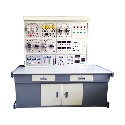
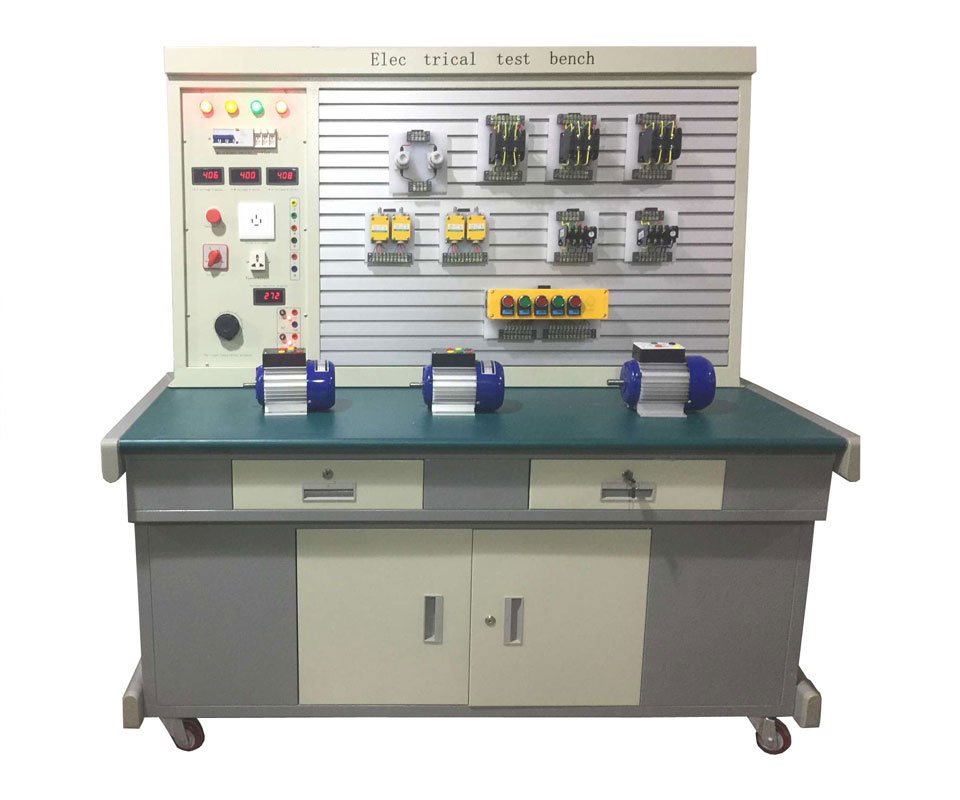
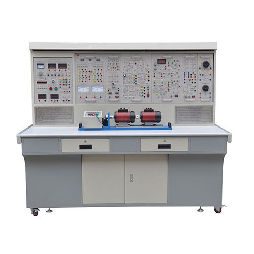
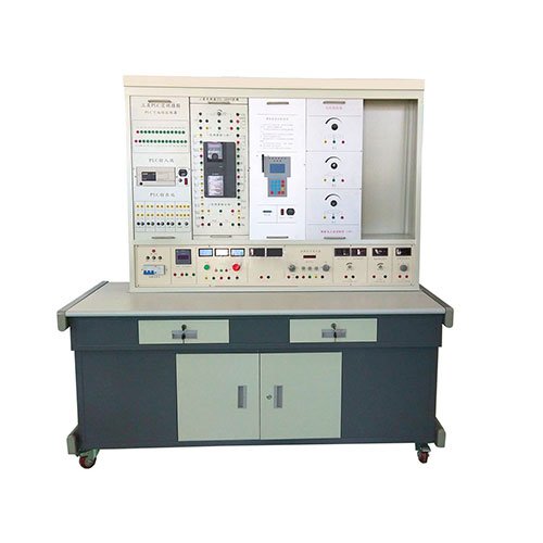
I. Structure
1. Laboratory Table: Made of imported melamine-faced panel, non-deforming and non-fading. Dimensions: 146×68×85cm
(1) General-Purpose Circuit Board: Fixed on the laboratory table surface for electronic experiments.
(2) Drawers: One on each side for storing commonly used tools.
(3) Component Storage Cabinet: For storing components.
2. Electronic Component Box: Contains transparent boxes for electronic components (see color illustration), for assembling experimental circuits on the general-purpose circuit board.
3. Fluorescent Lamp: 40W, used for fluorescent lamp circuits and power factor improvement experiments.
4. Control Cabinet: Dimensions: 144×30×26 (cm)
Main Components:
(1) Three-Phase Fuse:
Specification: Rated current 2A
Purpose: First protection device on the entire laboratory table.
(2) Current Input Indicator Light:
Specification: 220V neon bulb indicator light:
Purpose: Indicates the on/off state of the three-phase four-wire power supply and the laboratory table. (3) Residual Current Circuit Breaker (RCCB): Specifications: Three-phase four-wire system, rated current 3A, residual current action ≤30mA. Purpose: Provides short-circuit, overload, and residual current protection to ensure the safety of personnel and instruments.
(4) Power Output Indicator: Specifications: Three 220V neon indicator lights (red, green, and yellow). Purpose: The red, green, and yellow indicator lights illuminate when the switch is turned on.
(5) Three AC Voltmeters: Specifications: 0~450V. Purpose: Indicates the three-phase output voltage from 0 to 450V.
(6) I/O Switch: Controls the three-phase power output.
(7) Three-phase Power Output Port: Consists of two sets of four terminals (U, V, W, N) forming a three-phase four-wire power output port.
(8) Signal Source Unit: Outputs sine wave, square wave, and triangle wave waveforms.
(9) Pulse Source Unit: Outputs one set of positive and negative pulses.
(10) DC Regulated Power Supply: Outputs two independent, continuously adjustable DC regulated power supplies. (11) +5V Fixed Voltage Regulated Power Supply
(12) 3~24V Low Voltage AC Power Supply: Outputs 3, 6, 9, 12, 15, 18, and 24V low voltage common power supplies.
(13) Single-Phase Power Socket Set
Specifications: Each socket has a rated current of 2A.
Purpose: Provides several domestic and international standard single-phase 220V power sockets.
(14) Adjustable AC Power Supply:
Specifications: 1.5KVA three-phase voltage regulator
Purpose: Provides 0~380V continuously adjustable AC voltage, and can also provide 0~240V single-phase adjustable power.
(15) AC Voltmeter
Specifications: 0~450V
Purpose: Used to monitor the output voltage of the adjustable three-phase AC power supply.
(16) AC Power Output Socket: Uses terminal blocks: The output terminal of the adjustable AC power supply consists of 4 terminal blocks.
(17) Audio Amplifier
5. Experimental Screen
The experimental screen consists of experimental unit boards and an iron powder-coated frame. (1) Frame: The frame is divided into upper and lower layers and equipped with sliding tracks for easy assembly and disassembly of the experimental unit boxes, allowing for rapid movement.
(2) Experimental Unit Box: The unit box panel is injection molded, with components mounted on the back and fitted with a plastic protective cover to prevent students from touching live parts. The cover and panel are joined using a scientifically designed snap-fit structure for easy maintenance and disassembly. The panel is silkscreened with different component circuit symbols, and the component terminals are all led out from the terminals on the panel.
II. Main Technical Specifications
1. Input Power Supply: Three-phase five-wire
2. Output Power Supply and Signal:
(1) Unit A: Three-phase four-wire, with a fixed three-phase 380V power supply and a 0-380V three-phase adjustable output port.
(2) Unit B: AC 3, 6, 9, 12, 15, 18, 24V
(3) Unit C: Dual-channel regulated current and voltage power supply, with both output voltages ranging from 0 to 30V, continuously adjustable by multi-turn potentiometers, and featuring preset current limiting protection. Maximum output current is 2A. Voltage stability: <10⁻². Load stability: <10⁻². Ripple voltage: <5mV.
(4) D unit: DC regulated 5V, current 0.5A.
(5) F unit: 220V voltage output for external instruments.
3. Single pulse source: Outputs a pair of positive and negative pulses each time. 4. Function Signal Generator (Sine Wave, Triangle Wave, Rectangular Wave)
(1) Frequency Range: 5Hz-550KHz in five frequency bands
(2) Frequency Indication: Directly read from a Hz meter
(3) Voltage Output Range: Sine Wave: 5Hz-250KHz>4.5V, 250KHz-550KHz>3.5V Three-level attenuation: 0dB, 20dB, 40dB, with continuous fine adjustment
Rectangular Wave: 5Hz-250KHz>4.5V, 250KHz-550KHz>3.5V, amplitude continuously adjustable.
Triangle Wave: 5Hz-550KHz>1V
5. Audio Power Amplifier: Input audio voltage not less than 10mV, output power not less than 1W, adjustable volume, built-in speaker, used for amplification circuit amplification. Can also be used as a signal tracing instrument. 6. Insulation resistance: >5MΩ
7. Leakage protection: Leakage trip current ≤30mA
III. Equipment (Taking 24 seats as an example)
1. Experiment tables: 12 experiment tables (one table with two seats), dimensions: 148×68×85cm. A general-purpose circuit board (90×35cm) is mounted in the center of the tabletop for connecting experimental circuits. Component storage cabinets are located under the tables.
2. 24 stools
3. Control cabinets: 12 in total, one for each experiment table.
4. Experiment screens: 12 in total, one for each table.
5. Unit boards: 32 boards per unit, 384 boards for 24 seats.
6. 12 sets of DC meters, resistors, capacitors, transformers, diodes, transistors, integrated circuits, thyristors, sensors, etc., for electronic experiments. Components are already mounted in unit boxes.
7. One main power control console, controlling the power supply to each of the 12 student experiment tables.
8. Equipment: 12 MF-500 multimeters, 12 three-phase asynchronous motors (0.18KW), 24 soldering irons and soldering iron stands, 12 sets of needle-nose pliers, wire strippers, screwdrivers, 12 current plugs, and 480 self-locking experimental connecting wires.
9. User-provided equipment:
(1) Oscilloscope (model not limited); (2) Transistor millivoltmeter; (3) Slide wire rheostat; (4) Power meter
IV. Experimental Items
Electrical Engineering Experiments
1. Use of electrical measuring instruments
2. Identification and testing of common components
3. Irradiance characteristics of linear and nonlinear components
4. External characteristics of power supply
5. Determination of potential and voltage values
6. Range extension of ammeters and voltmeters
7. Verification of Kirchhoff’s laws
8. Verification of Lenz’s law
9. Verification of the Superposition Principle and Reciprocity Theorem
10. Verification of Thevenin’s Theorem and Norton’s Theorem
11. Equivalent Transformation of Voltage Sources and Current Sources
12. Study of Controlled Source Characteristics
13. First-Order Circuit Experiments
14. Transient Process of Second-Order Circuits
15. Study of the Characteristics of LC Elements in DC and AC Circuits
16. Conditions for a Load to Obtain Maximum Power
17. Measurement of AC Circuit Parameters
18. Characteristics of RLC Elements in Sinusoidal AC Circuits
19. RL and RC Series Circuit Experiments
20. RLC Series Resonant Circuit
21. Connection and Power Factor Improvement of Fluorescent Lamp Circuits
22. Star and Delta Connections of Three-Phase Loads
23. Three-Phase Circuits and Power Measurement
24. Study of R-C Frequency Selective Networks
25. Study of Two-Port Networks
26. Single-Phase Transformer Experiments
27. Mutual Inductance Circuit Experiments
28. 29. Application and Starting of Three-Phase Asynchronous Motors
30. Basic Circuit of Relay Contact Control for Three-Phase Motors
31. Experiment on Y-Δ Starting Control of Three-Phase Motors
32. Experiment on Sequential Control of Three-Phase Motors
33. Experiment on Energy Consumption Braking Control of Three-Phase Motors