- Automobile training equipment series
- Electrical and electronic teaching equipment
- Elevator training series
- Fitter training equipment
- Fluid mechanics experimental equipment
- Hydraulic and pneumatic test bench
- Mechanical teaching equipment
- Robotic automation and mechatronics series
- Welding training equipment

I. Technical Specifications
1. Input Power: Three-phase, five-wire, AC 380V ±10%, 50Hz
2. Storage Capacity: ≤1kVA
3. Dimensions: Reference value 1500×700×1300mm
4. Operating Environment: Temperature -10°C to +40°C, Relative Humidity 85% (25°C)
5. Safety Protection: Grounding protection, leakage protection (operating current <30mA), overload protection
II. Basic Components and Technical Parameters of the Experimental Device
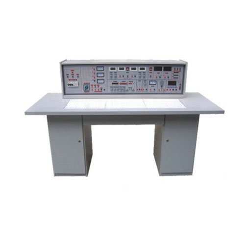
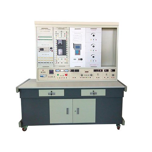
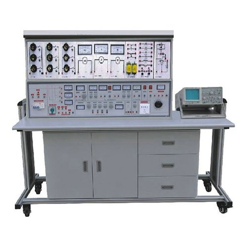
1. Experimental Table
The experimental table of the Advanced Electrical and Electronic Technology Experimental Device is constructed of aluminum alloy, offering a sturdy structure and elegant design. The tabletop is fireproof, waterproof, and wear-resistant high-density board with an insulating rubber mat. Drawers and small storage compartments are located underneath the table for storing tools, circuit modules, and materials. The table legs are nylon universal casters with brakes and a central support foot for both removable and fixed functionality. 2. Lab Bench
Each lab table is equipped with one lab bench. The bench top is made of imported PP injection molding.
3. Power Supply and Instrument Control Panel
The Advanced Electrical and Electronic Technology Experimental Device features a laser-engraved aluminum panel that provides an AC power supply, oscilloscope, signal source, indicator lights, indicator instruments, control switches, and buttons. Details are as follows:
1) Power Supply
1.1 Provides AC working power, outputting single-phase 220V AC and three-phase, four-wire 380V;
1.2 Equipped with a three-phase 0V to 380V continuously adjustable AC voltage regulator;
1.3 Equipped with a 220V single-phase AC power outlet with a five-hole panel.
1.4 One wireless digital receiver module receives control commands from the instructor, enabling wireless control of the student lab bench’s power supply.
1.5 Regulated DC output: ±12V/1.5A, 5V/1.5A. 1.6 DC regulated adjustable output: DC: 0-±24V/1A continuously adjustable output. Each power supply has short-circuit protection and automatic recovery.
2) Indicators, Display Instruments, and Control Buttons
2.1 Install three power indicator instruments. Switches indicate the grid input line voltage and the regulated output line voltage.
2.2 Install one power indicator light.
2.3 Install one main power control switch and one start/stop button.
2.4 Install one emergency stop button.
2.5 Install one set of short-circuit, leakage, and power failure alarms. 2.6 One digital AC ammeter, measuring range 0-500mA, 3.5-digit display, 0.5-level accuracy, and automatic range switching;
2.7 One digital AC voltmeter, measuring range 0-500V, 3.5-digit display, 0.5-level accuracy, and automatic range switching;
2.8 One digital DC voltmeter, measuring range 0-20V, with three ranges: 200mV, 20V, and 20V.
2.9 One digital DC ammeter, measuring range 200mA, with three ranges: 2mA, 20mA, and 200mA.
3) Low-frequency function signal generator
3.1 Outputs sine, square, triangle, and sawtooth waves, with a frequency range of 0-20MHz.
3.2 Four-pulse square wave output, 10ns-1s.
3.3 TTL/CMOS digital signal wave, 0-10MHz. 3.4 LCD1602 liquid crystal display.
4) Embedded LCD frequency counter
4.1 Frequency range 0-60 MHz, frequency resolution 0.01 Hz, output amplitude 6V.
4.2 LCD1602 liquid crystal display.
5) Embedded LCD dual-channel oscilloscope
5.1 Bandwidth: 100 MHz per channel. 5.2 Channels: Vertical dual independent channels + external trigger;
5.3 Sampling rate: Real-time sampling rate 1GSa/s;
5.4 Memory depth: 10MB;
5.5 Trigger modes: Edge, video, pulse width, slope, and alternating;
5.6 Vertical resolution: 8-bit (simultaneous sampling of both channels);
5.7 Automatic measurements: Peak-to-peak, mean, RMS, frequency, period, maximum, minimum, top, bottom, amplitude, overshoot, preshoot, rise time, fall time, positive pulse, negative pulse width, positive duty cycle, negative duty cycle, delay A→B, delay A→B; pass/fail test function.
5.8 Output interfaces: USB host (USB flash drive storage), USB device, LAN, AUX (trigger output/pass/fail). 5.9 Power Supply: 100-240VAC RMS, CAT II
5.10 Display: 8-inch TFT (true color) LCD, 65535 colors, 800 x 600 pixels.
5.11 Supports digital operations: addition, subtraction, multiplication, division, and FFT
5.12 Optional battery support for portability.
5.13 Fully automatic ranging function for instant measurement
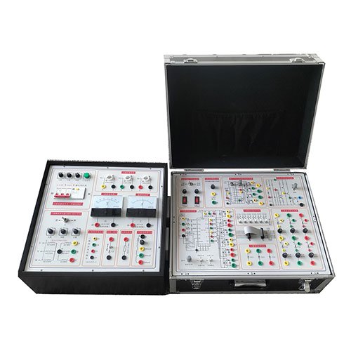
4. Experimental Hanging Box
1) Electrical Experimental Hanging Box (I)
1.1 Equipped with a three-phase, four-wire power switch with leakage protection.
1.2 Equipped with three short-circuit protection, three power indicator lights, three current connectors, and three-phase, four-wire power output terminals.
1.3 Accommodates three-phase lamp loads: three 15W bulbs per phase, controlled on and off by three switches, for a total of nine bulbs. Each phase is equipped with a current socket for convenient phase current measurement. 1.4 Fluorescent Lamp Component Set: Consists of a 10W ballast, a 10W fluorescent tube, a starter, and high-voltage capacitors for improving power factor (1µF/500V, 2.2µF/500V, and 0.47µF/500V).
1.5 R, L, and C Component Characterization Set: Consists of a 1kΩ/25W power resistor, a 1H/0.5A inductor, and a 4µF/500V high-voltage capacitor. These components can be tested experimentally.
1.6 Buck-boost iron-core transformer, 36V/220V. Current sockets on both the primary and secondary sides facilitate current measurement.
1.7 Dual-winding transformer, 220V/dual 12V. 2) Electrical Experiment Box (II)
2.1 Three 380V AC contactors (CJX2)
2.2 One thermal relay (JRS1D)
2.3 One time relay (JS14S)
2.4 Three control switches (with one normally open and one normally closed contact)
2.5 One 26V and one 6.3V transformer
2.6 One 10Ω/25W braking resistor and one bridge rectifier
2.7 One digital single-phase power and power factor meter, measuring range 0-500V, 0-2A, accuracy 0.5
2.8 One digital AC milliammeter, measuring range 0-200mA, 3.5-digit display, accuracy 0.5, automatic range switching
3) Circuit Principle Experiment Box
3.1 Constant current source: 0-50mA adjustable constant current source output with open circuit protection. 3.2 Safety Measures: A dedicated protection circuit board for the power input and output is designed, featuring ground fault protection, leakage overload and overcurrent protection, and misoperation protection. Safety measures comply with relevant national standards, and all materials meet environmental standards.
3.3 Experimental Module Configuration
1) Measurement of Component V/I Characteristics
2) Study of Potential in Circuits
3) Thevenin’s Theorem and Norton’s Theorem
4) Superposition Theorem and Reciprocity Theorem
5) Verification of Kirchhoff’s Laws
6) Study of Capacitor Charging and Discharging
7) Passive Two-Port Network
8) First-Order Dynamic Circuit
9) Second-Order Dynamic Circuit
10 Determination of AC Parameters
11) Series and Parallel Resonant Circuits
12) Controlled Source VCVZ and VCC Circuits
13) Gyrator Circuit
4) Digital Circuit Hanging Box
4.1 Commonly Used Digital Signals
1) Two sets of positive and negative single pulse generator circuits with level indicators are provided. 2) 1Hz-10kHz continuously adjustable clock circuit with two levels: 1Hz-100Hz and 100Hz-10kHz.
3) 9 fixed pulse outputs: 1Hz, 2Hz, 10Hz, 100Hz, 1kHz, 10kHz, 100kHz, 500kHz, and 1MHz. The 1Hz output has an indicator light.
4) 16-channel switch input and display circuit with input protection.
5) 16-channel switch output circuit with built-in display circuit at the output end to visually display the output status of the switch, and also with output protection.
6) 6-digit seven-segment common-anode LED digital display with built-in BCD code decoding circuit; 2 independent digital tubes, which can be equipped with common-anode or common-cathode digital tubes.
7) 2 sets of BCD code dial switch output circuits with output protection. 4.2 Testing Tools
1) Provides a three-state digital logic test circuit with audio and visual indicators.
4.3 Experimental Circuit Area: Designed with an independent circuit board, it is completely isolated from experimental signal sources to prevent damage to the main chassis from improper wiring during the experimental circuit area. The experimental circuit area is configured as follows:
1) An open experimental area with two IC8s, eight IC14s, two IC16s, one IC18, two IC20s, and one IC40 locking socket (compatible with IC28/IC24/IC18, etc.), and one potentiometer each of 100, 4.7K, 10K, and 100K.
2) Provides an independent 10MHz crystal oscillator, an 8Ω speaker, a buzzer, an ST135 photoelectric switch, and a 1×2 switch.
3) A set of wire test sockets is provided for measuring the continuity of experimental wires. 4) Multiple highly reliable locking, anti-folding sockets (internally connected to the integrated circuit socket, silver-plated copper tube, and fixtures) are provided as experimental connection and test points. When wiring, simply connect the locking plugs and wires.
5) Two expansion module circuit access areas: Each measures 155 x 100 mm and can be equipped with optional fixed-circuit experimental modules. This allows students to engage in innovative exercises to improve their thinking and practical skills.
6) Discrete components: resistors include 10Ω, 100Ω, 200Ω, 470Ω, 510Ω, 1K, 1.2K, 1.5K,
4.7K, 5.1K, 10K, 22K, 47K, 100K, 150K, 22M; 20P, 30P, 100 and 100P adjustable, 240P, 300P, 680P, 0.01uF, 0.02uF, 0.047 uF, 0.1uF, 10uF/16V, 47uF/16V, 100uF/16V; diodes 2AK2, 2CK13, 2CK15, IN4007; transistors 3DG6 and 3DK2; 32768Hz crystal oscillator; potentiometers (two each): 100K, 47K, 15K, 10K, 1K, and 330Ω; meeting the requirements for basic digital circuit experiments.
5) Analog Circuit Experiment Box
5.1 Low-voltage AC outputs: 0V, 14V, 16V, 18V, and dual 7.5V outputs with center taps. 5.2 DC signal source: Dual continuously adjustable -5V to +5V, -0.5V to +0.5V.
5.3 Experimental Module Circuits
1) Single-Stage Amplifier
2) Two-Stage Amplifier
3) Emitter Follower Circuit
6) Differential Amplifier
7) Negative Feedback Amplifier
8) Half-Wave, Full-Wave, and Bridge Rectifiers, Filters, and Shunt Regulators
9) Integrated Power Amplifier
10) Complementary Symmetrical Power Amplifier
11) Two Operational Amplifiers, which can be used to create various op-amp circuits
12) Discrete Component Area: Contains an 8Ω speaker, a bridge rectifier, a BT33 unijunction transistor, a 470µF capacitor and a 0.1µF capacitor, four 5.1V Zener diodes, a transistor connector, an integrated Zener diode connector, a 1W/51Ω resistor, and a 51K resistor. There is also an access area for discrete components such as diodes, capacitors, resistors, and transistors. Long silver-plated copper tubes serve as jacks to accommodate pins of varying sizes. 7. One 180W three-phase asynchronous motor: star/delta connection; aluminum alloy housing.
8. Experimental leads: 32 self-locking sheathed experimental leads (8 each of red, yellow, green, and black); 40 No. 2 experimental leads (10 each of red, yellow, green, and black).
9. Training tools:
Includes a 10mm Phillips screwdriver, a 10mm flat-blade screwdriver, 6-inch needle-nose pliers, 6-inch wire cutters, 6-inch wire strippers, 6-inch diagonal pliers, a bit handle, a socket, 18.5mm heavy-duty shears, and a soldering iron.
10. Innovative design module (one set per batch, from the same manufacturer as the electrical and electronic lab bench)
1) Simulated three-phase AC experimental model: This model simulates a three-phase AC power source using low-voltage DC power. The output three-phase AC power has adjustable voltage amplitude and phase difference, ensuring stability, reliability, safety, and energy conservation. This effectively avoids significant errors in experimental results caused by the uncertainty of the three-phase load of the entire power grid system (the three-phase load is random at every moment, resulting in unbalanced three-phase loads) and the non-zero internal resistance of the power supply system, which can lead to unbalanced and unstable three-phase power. This can affect experimental teaching efficiency and results. It conveniently observes the changes in neutral current caused by the three-phase voltage amplitude or phase difference changing from balanced to unbalanced, thereby deepening students’ understanding of three-phase electricity and increasing their learning interest. Using a load resistor in parallel with a light-emitting diode display circuit as each phase of the three-phase load ensures high load accuracy, energy conservation, long life, and enhanced personal safety.
2) Design of a safe power circuit model, including simulation of AC input safety voltage, neutral and ground fault protection circuits, an AC ammeter, an audible and visual alarm circuit, and an AC load.
11. Supporting Materials
One electronic and one paper set of the experimental instruction manual are provided. III. Experimental Projects
Meet all experimental syllabus requirements for electrical engineering, circuits, and electronic circuit technology, as detailed below:
1. Electrical Engineering and Circuit Analysis Experiments
1) Use of basic electrical instruments and calculation of measurement errors
2) Methods for reducing instrument measurement errors
3) Measurement and mapping of the volt-ampere characteristics of linear and nonlinear circuit components
4) Measurement of potential and voltage and plotting of circuit potential diagrams
5) Verification of Kirchhoff’s laws and fault diagnosis
6) Verification of the superposition theorem and fault diagnosis
7) Equivalent transformation of voltage and current sources
8) Verification of Thevenin’s theorem
9) Verification of Norton’s theorem
10) Verification of the reciprocity theorem
11) Experimental study of controlled sources
12) Observation and measurement of typical electrical signals
13) Response of first-order RC circuits Testing
14) Study of Second-Order Dynamic Circuit Response
15) Testing the Characteristics of RC Series and Parallel Frequency-Selective Networks
16) Study of R, L, and C Series Resonant Circuits
17) Gyrator Experiments
18) Negative Impedance Converter Experiments
19) Fluorescent Lamp Circuits and Power Factor Improvement
20) Y-Connection of Three-Phase Loads and Power Measurement of Three-Phase Circuits
21) Delta Connection of Three-Phase Loads and Power Measurement of Three-Phase Circuits
22) Testing the Frequency Characteristics of AC Components
23) RLC Series Resonant Circuits
24) Testing the Characteristics of Single-Phase Iron-Core Transformers
25) Measurement of Voltage and Current in Three-Phase AC Circuits
26) Measurement of Active Power in Three-Phase AC Circuits
27) Measurement of Power Factor and Phase Sequence in Three-Phase AC Circuits
28) Fluorescent Lamp Circuit Experiment
29) Three-Phase Squirrel Cage Asynchronous Motor Inching and Self-Lock Control
30) Three-Phase Squirrel Cage Asynchronous Motor Forward and Reverse Control
31) Three-Phase Squirrel Cage Asynchronous Motor Y-Δ Step-Down Starting Control
32) Three-Phase Squirrel Cage Asynchronous Motor Energy Consumption Control
33) Three-Phase Squirrel Cage Asynchronous Motor Sequence Control
34) Workbench Automatic Reciprocating Control
2. Analog Circuit Experiments
1) Basic Single-Stage Amplifier Circuit
2) Two-Stage Amplifier Circuit
3) Negative Feedback Amplifier Circuit
4) Differential Amplifier Circuit
5) Integrated Power Amplifier and Complementary Symmetric Power Amplifier Experiments
6) Rectification and Filtering Experiments
7) Series Voltage Regulator and Integrated Voltage Regulator Circuit Experiments
8) RC Sine Wave Oscillator
9) LC Oscillator and Frequency Selective Amplifier
10) Current/Voltage Conversion Circuit
11) Voltage/Frequency Conversion Circuit
12) Analog Operation Circuits: ① Voltage Follower ② Inverting Proportional Amplifier ③ Non-Inverting Proportional Amplifier ④ Inverting Summing Proportional Amplifier ⑤ Dual-Input Summing Amplifier Circuit
13) Integration and Differentiation Circuits: ① Integration Circuit ② Differentiation Circuit ③ Calculus Circuit
14) Waveform Generation Circuits: ① Square wave generator ② Rectangular wave generator with adjustable duty cycle ③ Triangle wave generator circuit ④ Sawtooth wave generator circuit
15) Active filter: ① Low-pass filter ② High-pass filter ③ Band-stop filter
16) Voltage comparator: ① Zero-crossing comparator ② Inverting hysteresis comparator ③ Non-inverting hysteresis comparator
17) Waveform conversion circuit
18) Operational amplifier performance test
3. Digital circuit experiments
1) Gate circuit logic function and testing experiment
2) Combinational logic circuit (half adder, full adder, and logic operation) design experiment
3) Trigger experiment (I) R-S, D, JK
4) Trigger experiment (II) Three-state output flip-flop, latch
5) Sequential circuit testing and research
6) Integrated counter and register experiment
7) Decoder and data selector experiment
8) Waveform generation and monostable flip-flop experiment
9) Gate circuit drive capability test experiment
10) CMOS gate circuit testing experiment
11) TS and OC gate function testing and application experiment
12) Experimental test of the performance and parameters of different TTL chip series
13) Experimental test of interconnecting TTL and CMOS
14) Experimental test of the MSI adder
15) Experimental test of the race to the limit
16) Experimental test of the application of triggers
17) Experimental test of registers and their applications
18) Application of the MSI counter chip
19) Experimental test of the sequential pulse and pulse distributor circuit
20) Experimental test of the Schmitt trigger and its application
21) Experimental test of the monostable trigger and its application
22) Experimental test of the dynamic scanning display of multi-digit LEDs
23) Experimental test of the traffic light control