- Automobile training equipment series
- Electrical and electronic teaching equipment
- Elevator training series
- Fitter training equipment
- Fluid mechanics experimental equipment
- Hydraulic and pneumatic test bench
- Mechanical teaching equipment
- Robotic automation and mechatronics series
- Welding training equipment

I. Configuration and Equipment (using a 24-seat laboratory as an example)
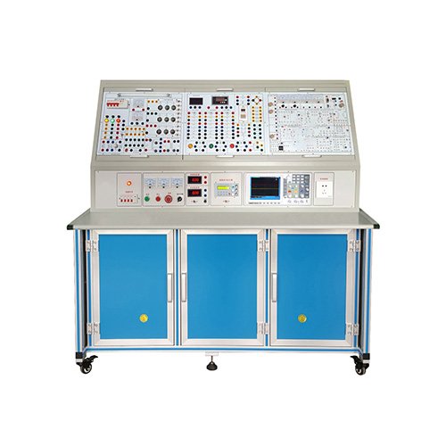
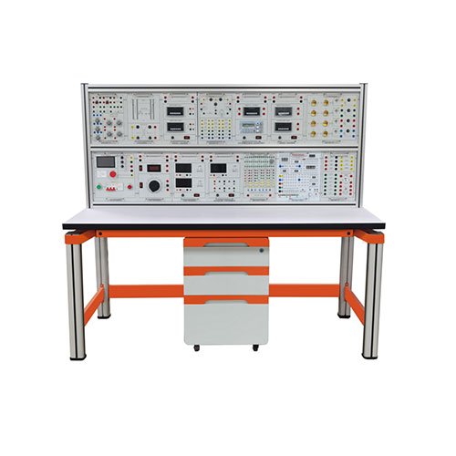
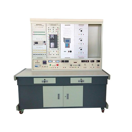
1. 12 experimental tables, each with two seats. A universal circuit board (35 x 90 cm) is located in the center of the tabletop. Component boxes can be assembled to create experimental circuits according to the experimental circuit. The transparent component boxes clearly display the components inside. The lids are printed with permanent component symbols, creating clear and attractive lines. The lids and bodies utilize a press-fit mechanism for easy maintenance and replacement. Each table is equipped with a rubber sheet to protect the universal circuit board surface (for use when placing motors, welding, etc.). Two component storage cabinets are located beneath the tables to store experimental components and the board.
2. 12 laboratory tables, with one per student’s table. 3. Teaching Console: Consists of a teaching experiment table, a lab bench, and a demonstration control screen, capable of controlling the power supply of 12 student lab benches. The demonstration screen, measuring 160 x 70 cm, stands on the bench and is used for explanations and demonstrations.
4. Equipment: 39 analog 1.5-level DC ammeters, 13 MF47 multimeters, 13 digital multimeters, 13 three-phase 180W motors, 26 time relays, 26 thermal relays, 65 AC contactors, 25 sets of circuit irons and soldering iron stands, 13 sets of wire strippers, needle-nose pliers, screwdrivers, and other tools, 13 sets of component boxes (with components already installed) for resistors, potentiometers, inductors, capacitors, transformers, bar magnets, logic level switches, and level indicators required for the experiments, 91 integrated sockets, 39 current test sockets, and 25 plastic stools.
5. User-Supplied Equipment: Dual-Trace Oscilloscope (any model), Sliding Variable Resistor, Millivoltmeter. II. Experimental Projects
(I) Electrical Engineering Experiments
1. Use of Electrical Measuring Instruments
2. Identification and Testing of Common Components
3. Volt-ampere Characteristics of Linear and Nonlinear Components
4. External Characteristics of Power Supplies
5. Determination of Potential and Voltage Values
6. Range Extension of Ammeters and Voltmeters
7. Verification of Kirchhoff’s Laws
8. Verification of Lenz’s Law
9. Verification of the Superposition Principle and the Reciprocity Theorem
10. Verification of Thevenin’s Theorem and Norton’s Theorem
11. Equivalent Transformation between Voltage and Current Sources
12. Study of Controlled Source Characteristics
13. First-Order Circuit Experiments
14. Transient Processes in Second-Order Circuits
15. Study of the Characteristics of LC Elements in DC and AC Circuits
16. Conditions for Maximum Power to a Load
(II) Analog Section
1. Forward and Reverse Phase Characteristics of Diodes
2. Input and Output Characteristics of Transistors
3. Transistor Common Emitter Single-Transistor Amplifier
4. Two-Stage Resistor-Capacitor Coupled Amplifier Circuit
5. The Effect of Negative Feedback on Amplifier Performance
6. Field-Effect Transistor Amplifier
7. Differential Amplifier Circuit
8. Operational Amplifier Specification Testing
9. Basic Applications of Integrated Operational Amplifiers
(Various Analog Operational Circuits)
10. Nonlinear Applications of Integrated Operational Amplifiers
(Various Waveform Generators)
(III) Digital Section
1. Parameter Testing of TTL Integrated Logic Gates
2. Parameter Testing of CMOS Logic Gates
3. Applications of TTL Integrated Open-Channel Gates and Tri-State Output Gates
4. AND, NOT, OR, and NAND Gate Circuit Experiments
5. Half Adder Circuit Experiments
6. Full Adder Circuit Experiments
7. RS Flip-Flop Experiments
8. D Flip-Flop Experiments
9. JK Flip-Flop Experiments
10. T Flip-Flop Experiments
11. Converting a JK Flip-Flop to a D Flip-Flop
12. Converting a D Flip-Flop to a JK Flip-Flop
13. Counter Experiment
14. MSI Shift Register and Its Application
15. Decoder and Its Conversion Method