- Automobile training equipment series
- Electrical and electronic teaching equipment
- Elevator training series
- Fitter training equipment
- Fluid mechanics experimental equipment
- Hydraulic and pneumatic test bench
- Mechanical teaching equipment
- Robotic automation and mechatronics series
- Welding training equipment
Anodized aluminum frame and panels made of painted steel.
The unit includes wheels to facilitate its mobility.
Main metallic elements made of stainless steel.
Diagram in the front panel with distribution of the elements similar to the real one.
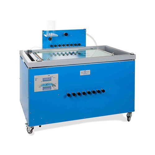
Laminar flow visualization table.
Flow visualization area.
Eight sources and eight sinks.
Sinks and sources control valves.
Input control valves.
Dye tank.
Dye manifold.
Drain valve.
Grid to facilitate the visualization of the lines of flow.
The top glass sheet of the visualization area has handles to lift it easily for a correct operation or to install the different hydrodynamic models.
The central sink of the bottom plate, placed in the visualization area, has a doublet, that is to say, there is a sink and source in close proximity.
The control systems allow every sink and source or only some of them to be fed at the same time.
It is supplied with a dye injection system, for a better visualization of the flow lines. It consists of nineteen needles, placed between the glass sheets at the input. They are feed from a simple adapter. An appropriate quantity of dye is injected through each needle and the direction is clearly visualized.
It includes a set of hydrodynamic models:
Three circular models: 40, 60 and 80 mm diameter.
Three square models: 40, 60 and 80 mm of length.
Wing shaped model.
The unit can be completely drained by opening the drain valves located on the base of the input and output tanks.
Manuals: This unit is supplied with the following manuals: Required Services, Assembly and Installation, Starting-up, Safety, Maintenance & Practices Manuals.
Unit: – Dimensions: 1600 x 1000 x 1250 mm approx. (62.99 x 39.37 x 49.21 inches approx.) – Weight: 60 Kg approx. 132 pounds approx.)
Work area: – Dimensions: 605 x 900 mm approx. (23.81 x 35.43 inches approx.)
EXERCISES AND PRACTICAL POSSIBILITIES
Ideal flow around immersed bodies:
1.- Ideal flow around a cylinder.
2.- Ideal flow around a surface.
3.- Ideal flow around a bluff body.
Ideal flow in channels and edges:
4.- Ideal flow in a convergent channel.
5.- Ideal flow in a divergent channel.
6.- Ideal flow through a 90º bend.
7.- Ideal flow through a sudden contraction.
8.- Ideal flow through a sudden broadening.
9.- Replacement of a streamline by a solid boundary.
Ideal flow associated to sinks and sources:
10.- Formation of a Rankine half-body.
11.- Formation of a Rankine oval.
12.- Superposition of sinks and sources.


