- Automobile training equipment series
- Electrical and electronic teaching equipment
- Elevator training series
- Fitter training equipment
- Fluid mechanics experimental equipment
- Hydraulic and pneumatic test bench
- Mechanical teaching equipment
- Robotic automation and mechatronics series
- Welding training equipment

(I) Overview
This device is suitable for the electrical control circuits required by textbooks such as “Junior Maintenance Electrician,” “Intermediate Maintenance Electrician,” “Advanced Maintenance Electrician,” “Electrical and Electronics Training,” and “Advanced Machine Tool Circuit Assessment.” Through the device’s equipped PLC and variable frequency drive, along with corresponding training modules, students can quickly master the practical application techniques and operational skills required by the courses. This targeted, practical, scientific, and advanced training device meets the requirements of technician skills and the intermediate and advanced maintenance electrician assessment syllabi. (II) Device Features:
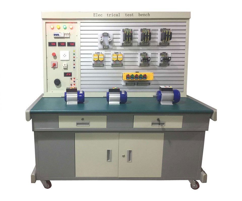
1. Electrical control circuit components are mounted on a mounting plate that serves as a hanging plate, making them easy to operate and replace, facilitating functional expansion or the development of new training sessions. The selection of operational content is both typical and practical.
2. The control panel requires only a three-phase, four-wire AC power supply for operation.
3. The control circuits and specially designed small motors used for skills training simulate various electrical drive systems found in factories and meet the technical requirements for installation, commissioning, troubleshooting, and troubleshooting for maintenance electricians.
4. The device is equipped with voltage-type and current-type leakage protection devices to ensure operator safety.
5. All components are connected to terminal blocks via wires, allowing students to connect only to the terminals, which helps protect the components.
6. Wiring is routed through wiring troughs, enabling process wiring training. ▲(III) Technical Performance:
1. Input Voltage: Three-phase four-wire (or three-phase five-wire) ~380V ±10% 50Hz
2. Operating Environment: Temperature -10°C to +40°C, Relative Humidity <85% (25°C), Altitude <4000m
3. Device Capacity: <1.5KVA
4. Weight: Approximately 100kg
5. Dimensions: No more than 1300×70×1500mm
6. Leakage Protection Trigger Current: ≤30mA; Leakage Protection Trigger Time: ≤0.1s.
(IV) Basic Configuration and Functions of the Device
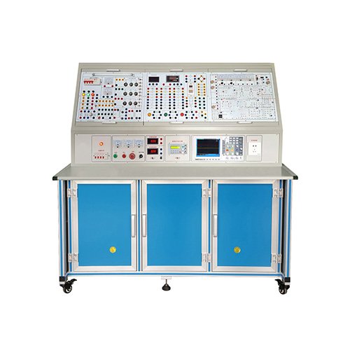
1. Power Control Box: The main control panel is constructed of double-layered matte, fine-grained plastic-sprayed iron with an aluminum panel. The entire training room is equipped with a master power control cabinet, which controls the power supply to each device below. 2. Resources equipped on the main control function board
(1) Three-phase four-wire power input, after passing through the leakage protector, through the main switch, and operated by the contactor through the start and stop button;
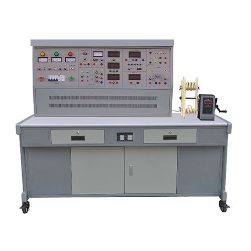
(2) Three 450V pointer-type AC voltmeters are provided to indicate the three-phase voltage of the power input;
(3) Low-voltage AC voltage 3-24V is adjustable in seven levels, with a maximum output current of 1.5A, and ammeter indication.
(4) Dual-channel regulated power supply, both output voltages are 0-30V, continuously adjusted by potentiometers, with a maximum output current of 1.5A, and each power output has a 0.5-level digital ammeter. Voltmeter indication. Voltage stability <10-2, load stability <10-2, ripple voltage: <5mV.
(5) Constant current source: 0–200mA continuously adjustable, digital meter display, open circuit protection. (6) Function signal generator: (1) Waveform: sine wave, triangle wave, square wave. (2) Frequency range: 5Hz-550KHz continuously adjustable in sections. (3) Sine wave distortion: 10Hz-100KHz less than 1%. (4) Output amplitude: sine wave greater than 0-14Vp-p. (7) Frequency meter: Measuring range is 1Hz to 8MHz, with a six-digit LED digital tube display, a gate time base of 1S, and a sensitivity of 35mV. Switch (internal measurement/external measurement) conversion. (8) Power: Power factor meter: It is composed of a microcomputer, a high-precision A/D conversion chip, and a full digital display circuit. The human-computer dialogue function control mode is realized through key control and digital display window. In order to improve the measurement range and test accuracy, the hardware and software are divided into eight gear areas, with automatic judgment and automatic gear shifting. Power measurement accuracy is Class 1.0, with voltage and current ranges up to 450V and 5A, respectively. When measuring power factor, it automatically determines the load type (displays “L” for inductive, “C” for capacitive, and no display for purely resistive). Up to 15 sets of data can be stored for easy access.
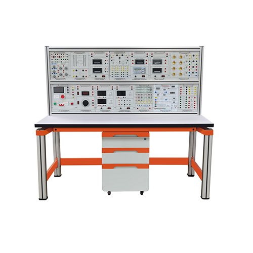
3. Training Bench: The entire frame is made of sheet metal, precision-machined by CNC machinery, and the exterior is electrostatically oxidized. The bench connectors utilize an integrated welded design, resulting in a stylish and durable design. The bench includes a component storage cabinet with universal casters with brakes at the bottom, allowing for both mobile and stationary operation.
The experimental work surface, constructed of industrial profiles, connects the bench to the power control panel. It features a built-in area for machine tool electrical modules and a steel frame with a spray-coated exterior.
Below the work surface, a component and tool drawer is located, featuring silent three-section slides made of high-quality steel. 4. Composition and Functional Description of Wireless Network Intelligent Assessment System
(1) The system consists of a teacher’s computer (prepared by the user), a wireless network module (with host computer management software) and an intelligent human-machine platform (student answering device), which form an intelligent training assessment system through a wireless network.
(2) The teacher edits the test paper on the computer and edits the fault point according to the training assessment requirements. The set fault point is sent to the human-machine platform (student answering device) on each student training assessment device through the intelligent assessment system through the wireless network, and the set fault point is automatically generated on the machine tool circuit.
(3) Answering function: According to the fault point set by the system, the corresponding fault phenomenon is generated after the circuit is operated. The assessment judges the fault point based on the phenomenon and inputs the judgment result into the student computer. When the student finishes the test and presses the submit button, the system will immediately give the test score according to the answer on the test paper of the candidate and save the score in the candidate’s file.
(4) The teacher can monitor the test process of the candidate on the computer and monitor the answer of each student. After the exam, students’ scores can be sorted, archived, and printed. (5) The intelligent human-computer platform (answering machine) consists of a Chinese LCD display, a microcomputer control circuit, and a keyboard. (6) System intelligence: The teacher’s computer sets the faults (random faults and specified faults) in a unified manner, and transmits them to the student training station via the wireless network for troubleshooting training or assessment. The fault point setting is quick and convenient, and the training and assessment results are automatically recorded, sorted, and printed, which greatly facilitates the management of the training room and greatly reduces the workload of teachers. Fair results: The computer sets the faults in a unified manner, and the conditions and opportunities for training and assessment personnel are equal. The training and assessment results are judged objectively and scientifically, ensuring the fairness and justice of the assessment results. Practical training: By combining with different training equipment, students can be trained to connect training circuits and master practical skills. At the same time, the intelligent assessment system can be used to scientifically and fairly assess the professional knowledge learned by students, effectively improving the school’s training and assessment management capabilities. High stability: The system uses an independent switching power supply, the circuit design is optimized and reasonable, and the production process is strictly and perfect to ensure the reliability and stability of the machine. Highly Practical: Through testing, users can locate fault points and gain a thorough understanding of the characteristics of various machine tool failures, the performance and structure of various components, and the operating principles of machine tool circuits.
Easy Networking: All data exchange in this system is transmitted via a wireless network, allowing for quick and easy networking and the addition of any number of networked devices (up to 255). This eliminates the need for tedious network cabling, significantly simplifying laboratory installation and reducing costs.
5. Free Simulation Software: Multimedia 3D Simulation Teaching Software
Utilizing 3D virtual simulation technology, users can observe component details from a 360-degree perspective. Multimedia animations showcase the structure, function, operating principles, and control methods of various components. Interactive simulation animations allow for circuit assembly, debugging, and troubleshooting, enabling hands-on learning of common instruments and equipment, electrical testing, and motor control techniques involved in electrical equipment. Including but not limited to:
(1) Experimental equipment
Using 3D modeling, the components used in the training equipment are realistically displayed to students, giving them an intuitive understanding.
(2) Typical circuits The schematic diagram and physical wiring diagram of the corresponding circuit of the training equipment will be reflected in this column. Click the corresponding component symbol on the schematic diagram with the mouse, and the corresponding device will be indicated in the real circuit, and the function of the component in the circuit will appear in the prompt window.
(3) Circuit principle The circuit working principle of the circuit is explained with vivid animation demonstration and professional voice explanation, which makes the teaching courseware reach a certain depth. The boring principle teaching becomes vivid and easy to understand, which is one of the most powerful teaching tools for teachers.
(4) Wiring practice Students simulate the wiring of the circuit according to the prompts on the semi-transparent schematic diagram. The system also has corresponding prompts while wiring. It can train students’ standard wiring and provide them with familiarity with the circuit.
(5) Experimental simulation
Students can operate air switches, buttons and other components to control the circuit of the corresponding project. The contactors, time relays and other components on the interface can control the rotation of the motor according to the operation. 6. Basic knowledge and operation of electrical engineering: (1) Knowledge of safe use of electricity, common electrical tools, common wire connections and manual welding processes. (2) Electrical drawing recognition: Introduces the electrical symbols of common components, principles of schematic drawing, analysis methods, principles of wiring diagram drawing, and relative numbering methods. (3) Electrical instruments: Introduces the appearance, structure, panel and usage methods of common electrical instruments such as multimeters, energy meters, clamp-on ammeters, megohmmeters, DC bridges and distribution boards. (4) Lighting circuit installation: Introduces the relevant knowledge of fluorescent lamps and two-way control lamps from the five aspects of components, circuits, principles, wiring and troubleshooting. (5) Low-voltage electrical appliances: Introduces common low-voltage electrical appliances such as AC contactors, relays, common knife switches, low-voltage circuit breakers, fuses, starters, and master electrical appliances from the five aspects of appearance, structure, principle, assembly and testing. (6) Motors and Transformers: Mainly explains the appearance, structure, assembly and maintenance of three-phase asynchronous motors, single-phase asynchronous motors, servo motors, stepper motors, DC motors and transformers.
(7) Motor Control: Explains the common motor control methods according to the actual circuit development process. Including components, principles, circuits, layout, wiring, operation, troubleshooting and other contents.
(8) User Manual: Instructs users on how to use this system.
7. Training Connection Cables: According to the characteristics of different training projects, two different specifications of training connection cables are equipped. Both strong and weak current use high-reliability sheathed structure and are plugged with a gun (there is no possibility of electric shock). The oxygen-free copper wire is drawn into a multi-strand wire as thin as a hair to achieve the purpose of ultra-softness. The outer layer is covered with a butyl nitrile polyvinyl chloride insulation layer, which has the advantages of softness, high voltage resistance, high strength, anti-hardening and good toughness. The plug uses a solid copper piece with a beryllium light copper shrapnel, which is safe and reliable. Both wires can only be used with sockets with corresponding inner holes and cannot be mixed. ▲(V) Practical Training Project Requirements:
Experiment 1: AND, OR, and NOT Logic Function Experiment
Experiment 2: Timer Function Experiment
Experiment 3: Counter Function Experiment
Experiment 4: Transfer Instruction Function Experiment
Experiment 5: Data Shift Instruction Function Experiment
Experiment 6: Arithmetic Operation Instruction Function Experiment
Experiment 7: Motor Control Experiment
Experiment 8: LED Digital Tube Experiment
Experiment 9: Traffic Light Control
Experiment 10: Water Tower Water Level Automatic Control
Experiment 11: Automatic Molding Machine
Experiment 12: Automatic Rolling Mill
Experiment 13: Automatic Mixing of Multiple Liquids
Experiment 14: Automatic Feeding and Loading System
Experiment 15: Mail Sorting Machine
Experiment 16: Elevator Control
Experiment 17: Robot Control
Experiment 18: PLC Control of Four-Section Conveyor Belt Simulation Control
Experiment 19: PLC Control of Automatic Beverage Vending Machine
Experiment 20: PLC Control of Four-Channel Buzzer System
Experiment 21: PLC Controlling the Electroplating Workshop Production System
Experiment 22: PLC Control of Tool Library Selection in a Machining Center
Experiment 23: PLC Control of the Light Tower
Practical Training 24: PLC Control of State Transfer and Branching Functions
Practical Training 25: PLC Control of Data Processing Instruction Functions
Practical Training 26: PLC Control of Differential and Bit Operation Functions
Practical Training 27: PLC Control of Artistic Lantern Designs
Practical Training 28: PLC Control of Inching and Self-locking Control of a Three-Phase Squirrel Cage Asynchronous Motor
Practical Training 29: PLC Control of Linked Forward and Reverse Control of a Three-Phase Squirrel Cage Asynchronous Motor
Practical Training 30: PLC Control of Automatic Reciprocating Control of a Three-Phase Squirrel Cage Asynchronous Motor
Practical Training 31: PLC Control of Y/△ Switching Starting Control of a Three-Phase Squirrel Cage Asynchronous Motor
Practical Training 32: PLC Control of Series Resistor Voltage Drop Starting Control of a Three-Phase Asynchronous Motor
Practical Training 33: PLC Control of Energy-Consumption Braking Control of a Three-Phase Asynchronous Motor
Practical Training 37: Understanding VFDs and Setting and Operating Functional Parameters
Practice 38: VFD Panel Control Operations
Practice 39: VFD Speed Control of Three-Phase Asynchronous Motors
Practice 40: Z35 Radial Drilling Machine Electrical Control Operations
Practice 41: CA6140 Lathe Electrical Control Operations
Practice 42: X62W Universal Milling Machine Electrical Control Operations
Practice 43: T68 Horizontal Boring Machine Electrical Control Operations
Practice 44: Z35 Radial Drilling Machine Electrical Troubleshooting and Troubleshooting
Practice 45: CA6140 Lathe Electrical Troubleshooting and Troubleshooting
Practice 46: X62W Universal Milling Machine Electrical Troubleshooting and Troubleshooting
Practice 47: T68 Horizontal Boring Machine Electrical Troubleshooting and Troubleshooting
▲(VI) Electrical control circuit fault descriptions for various machine tool modules:
1. CA6140 lathe circuit fault:
① Spindle phase loss
② Control transformer primary line power loss
③ Control circuit power loss, open circuit between FU4 and FR1
④ Control circuit power loss, open circuit between FR1 and FR2
⑤ Spindle unable to start
⑥ Spindle unable to self-lock
⑦ Spindle unable to start, KM1 coil power loss
⑧ Coolant pump unable to start
⑨ Coolant pump unable to start
⑩ Tool turret unable to move
2. X62W milling machine circuit fault:
① Control circuit power loss of 110V, control circuit failure, open circuit between fuse and FR1
② Control circuit power loss of 110V, control circuit failure, open circuit between FR3 and SA5-1
③ Tool turret rapid movement unable, KM4 coil power loss
④ Worktable rotary table operation unable to start, FR2 and Circuit break between SA1-1 and SQ6-1
⑤ The worktable cannot start; power is lost to the upper port of SA1-3
⑥ The worktable cannot start in the left, up, or backward directions; power is lost to the KM2 coil
⑦ The worktable cannot start in the right, down, or forward directions; power is lost to the KM3 coil
⑧ Spindle braking cannot be completed; power is lost to the rectifier circuit
⑨ Spindle braking cannot be completed; power is lost to the brake coil
⑩ Lighting circuit power is lost
3. T68 boring machine circuit failure:
① Control circuit failure; no 110V voltage
② Spindle forward rotation cannot start; circuit between KA1 coil and KA2 normally closed is open
③ Spindle reverse rotation cannot start
④ Braking failure
⑤ Step-down starting circuit failure
⑥ Time relay power is lost; △/Y Startup failed.
⑦ Spindle failed to start at low speed.
⑧ Spindle failed to start at high speed.
⑨ Rapid traverse motor failed to start in reverse.
⑩ Rapid traverse motor failed to start in reverse.
4. Z35 Radial Drilling Machine Circuit Fault:
① Control circuit power loss of 110V, control circuit failure, transformer primary open.
② Control circuit power loss of 110V, control circuit failure, Fu4 input open.
③ Control circuit power loss of 110V, control circuit failure, open circuit between Fu4 and FR.
④ Protective relay KV not activated, control circuit failure, open circuit between FR and SA.
⑤ Power indicator 6.3V not on, SA3 and transformer 6.3V secondary open.
⑥ Spindle motor not activated, KM1 coil lost power.
⑦ Rocker arm not rising, KM2 coil lost power.
⑧ Rocker arm not lowering, KM3 coil lost power.
⑨ Column clamping not activated, KM4. Coil de-energized
⑩ The column does not release. KM5 coil de-energized.