- Automobile training equipment series
- Electrical and electronic teaching equipment
- Elevator training series
- Fitter training equipment
- Fluid mechanics experimental equipment
- Hydraulic and pneumatic test bench
- Mechanical teaching equipment
- Robotic automation and mechatronics series
- Welding training equipment

I. Experimental Content:
A. Crank-Guide-Slider Mechanism
1. Crank Motion Simulation and Testing
2. Slider Motion Simulation and Testing
3. Crank Speed Fluctuation Control
B. Crank-Slider Mechanism
1. Crank-Slider Mechanism Design
2. Crank-Slider Motion Simulation and Testing
3. Slider Motion Simulation and Testing
4. Crank Speed Fluctuation Control
C. Disc Cam Mechanism
1. Cam Motion Simulation and Testing
2. Push Rod Motion Simulation and Testing
3. Master Planar Mechanism Structure Assembly and Motion Control
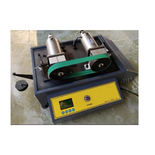
II. Main Configuration and Parameters:
1. Detection System
2. Test Sensors:
Angular Displacement Sensor: Output Voltage: 0-5V, Pulse Count: 1000P (2 units)
Linear Displacement Sensor: Output Voltage: 0-5V, Range: 160L (1 unit)
3. Power and Control
DC Motor: ≥120W, Spindle Speed Range: 0-250rpm
4. Test Software: 1 set developed using the LabVIEW platform.
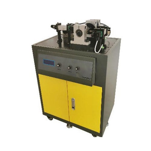
5. Dimensions: Approximately 480 × 480 × 760 mm
6. Weight: Approximately 65 kg