- Automobile training equipment series
- Electrical and electronic teaching equipment
- Elevator training series
- Fitter training equipment
- Fluid mechanics experimental equipment
- Hydraulic and pneumatic test bench
- Mechanical teaching equipment
- Robotic automation and mechatronics series
- Welding training equipment

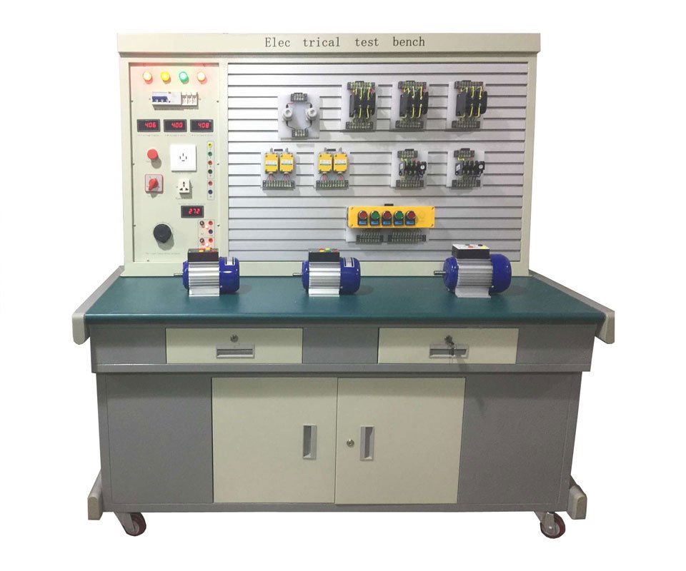
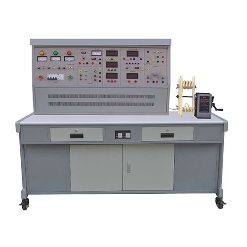
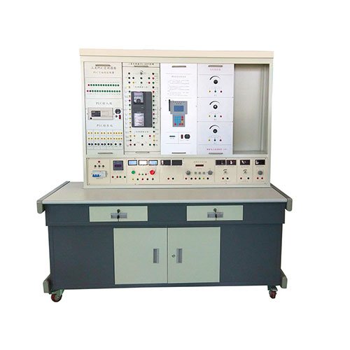
Adopts hanging box structure, concise and clear, reasonable layout, convenient and flexible use. The experimental instrument is fully digitally displayed and has high precision. It takes reliable protection for the power supply and instruments involved in the experiment, and sets up a reliable personal safety protection system.
Use: Applicable to the experimental teaching of courses such as “Electrical Basics”, “Electrical Engineering”, “Digital Electronics”, and “Analog Electronics” in colleges and universities. And it can expand the experimental content such as “Programmable Controller” and “Motor Frequency Control”.
(I) Supporting learning simulation software: “Electrical Skills and Training Simulation Teaching System Software”, “Electronic Skills and Training Simulation Teaching System Software” (Computer users prepare by themselves, please specify if configuration is required)
1. Experimental equipment
Use 3D modeling to make the components used in the training equipment truly projected to students, so that students have a more intuitive understanding.
2. The schematic diagram and physical wiring diagram of the corresponding circuit of the typical circuit training equipment will be reflected in this column. Click the corresponding component symbol on the schematic diagram with the mouse, and the corresponding device will be indicated in the real circuit, and the role of the component in the circuit will appear in the prompt window
3. Circuit principle The circuit working principle of the circuit is explained with vivid animation demonstration and professional voice explanation, which makes the teaching courseware reach a certain depth. The boring principle teaching becomes vivid and easy to understand, which is one of the most powerful teaching tools for teachers.
4. Wiring practice Students simulate the wiring of the circuit according to the prompts on the translucent schematic diagram, and the system also has corresponding prompts while wiring. It can train students’ standardized wiring and provide familiarity with the circuit
5. Experimental simulation
Students can operate air switches, buttons and other components to control the circuit of the corresponding project. The contactors, time relays and other components on the interface can control the rotation of the motor according to the operation.
The electrical skills and training simulation system uses 3D virtual simulation technology, allowing users to observe the appearance details of devices at 360 degrees without blind spots; multimedia demonstration animations are used to display the structure, function, working principle and control method of various components; through interactive simulation animations, circuit assembly, debugging and troubleshooting are carried out, so as to achieve the practical operation skills and precautions of common instruments and equipment, electrical detection and motor control involved in electrical equipment related majors without physical objects. Including but not limited to:
(1) Basic knowledge and operation of electrical workers: common knowledge of safe use of electricity, common electrical tools, common wire connections and manual welding processes.
(2) Electrical drawing recognition: introduces the electrical symbols of common devices, principles of schematic drawing, analysis methods, principles of wiring diagram drawing, and relative numbering method.
(3) Electrical instruments: introduces the appearance, structure, panel and use methods of common electrical instruments such as multimeters, energy meters, clamp-type ammeters, megohmmeters, DC bridges and distribution boards.
(4) Lighting circuit installation: Introduces the relevant knowledge of fluorescent lamps and two-location control lamps from the five aspects of devices, circuits, principles, wiring and troubleshooting.
(5) Low-voltage electrical appliances: Introduces common low-voltage electrical appliances such as AC contactors, relays, common knife switches, low-voltage circuit breakers, fuses, starters, and master electrical appliances from the five aspects of appearance, structure, principle, assembly and detection.
(6) Motors and transformers: Mainly explains the appearance, structure, assembly and maintenance of three-phase asynchronous motors, single-phase asynchronous motors, servo motors, stepper motors, DC motors and transformers.
(7) Motor control: Explains the common motor control methods according to the actual circuit development process. Including devices, principles, circuits, layout, wiring, operation, troubleshooting and other contents.
(8) User manual: Instructs users on how to use this system.
(II) Technical indicators and instructions:
▲1. Dimensions: not more than 1300×700×1500mm
2. Working power supply: AC three-phase four-wire 380±5% 50HZ
3. Input power: <1.5KVA
4. Output AC power supply: three-phase four-wire 380V, single-phase 0–250V continuously adjustable, voltage and current meter indication; Configure intelligent alarm system:
The alarm system uses LED display to monitor the voltage, current and temperature values of the training equipment in real time when it is powered on. Before the students conduct the experiment, the teacher can set the warning value of the intelligent alarm according to the specific experimental project. If there is an experimental error or wiring error during the student’s experiment, the system will automatically sound and light alarm and automatically cut off the power supply. Teachers can freely choose to turn on or off the intelligent alarm system according to the needs of the experiment. The intelligent alarm system has remote communication and monitoring functions, and is equipped with an extended fire alarm function.
5. Personal safety protection function: current leakage protection, voltage leakage protection and anti-electric shock experimental wire.
6. DC regulated power supply: two groups of 0–30V continuously adjustable, automatic relay shifting, digital meter display, automatic overload protection, indication and automatic recovery functions.
7. Constant current source: 0–200mA continuously adjustable, digital meter display, open circuit protection.
8. Timer and alarm recorder: The power control panel is equipped with a timer and alarm recorder, which has the functions of setting the experimental time and recording the number of alarms.
9. Function signal generator:
1) Waveform: sine wave, triangle wave, square wave.
2) Frequency range: 5Hz-550KHz segmented continuously adjustable.
3) Sine wave distortion: 10Hz-100KHz less than 1%.
4) Output amplitude: sine wave greater than 0-14Vp-p.
Frequency meter: The measurement range is 1Hz to 8MHz, with a six-digit LED digital tube display, a gate time base of 1S, and a sensitivity of 35mV. Switch (internal measurement/external measurement) conversion.
10. DC digital voltmeter: microprocessor-made; 0.5-level accuracy; measurement range: 0-300V.
11. DC digital milliammeter: microprocessor-made; 0.5-level accuracy; measurement range: 0-500mA.
12. DC digital ammeter: microprocessor-made; 0.5-level accuracy; measurement range: 0-5A.
13. AC digital voltmeter: latest professional MCU-made; 0.5-level accuracy, measurement range: 0-450V.
14. AC digital ammeter: latest professional MCU-made; 0.5-level accuracy, measurement range: 0-5A.
15. Training connection wire: According to the characteristics of different training projects, two different specifications of training connection wires are equipped. Both strong and weak electricity use high-reliability sheath structures and are connected by guns (there is no possibility of electric shock). The oxygen-free copper wire is drawn into a hair-thin multi-strand wire to achieve the purpose of ultra-softness. It is covered with a nitrile polyvinyl chloride insulation layer, which has the advantages of softness, high pressure resistance, high strength, anti-hardening, and good toughness. The plug uses a solid copper piece with a beryllium light copper shrapnel, which is safe and reliable to contact; both wires can only be matched with the sockets of the corresponding inner holes and cannot be mixed, which greatly improves the safety and rationality of the training.
16. Experimental hanging box: The front of the experimental hanging box panel is printed with schematics and symbols, and the corresponding components are welded on the back. The parts that need to be measured and observed are equipped with locking connectors, which are easy to use, intuitive and reliable. The experimental circuit is designed in a unit circuit manner. Each unit circuit is based on the basic circuit, and then different components are connected to the circuit parameters or through different unit circuit combinations to complete different experimental requirements.
(1) Electrical experiment hanging box 1
It is equipped with RC series-parallel frequency selection network experimental circuit, Thevenin theorem/Norton theorem experimental circuit, RLC series resonance experimental circuit, Kirchhoff/superposition theorem experimental circuit, first-order and second-order experimental circuit, two-port network, and reciprocity theorem experimental circuit. The front of the hanging box panel is printed with schematic diagrams and symbols, and the back is welded with corresponding components. It is convenient, intuitive, and reliable to use.
(2) Electrical experiment hanging box 2
It is equipped with instrument range expansion experimental circuit, circuit state trajectory observation experimental circuit, maximum power transmission condition determination experimental circuit, RC double T frequency selection network experimental circuit, voltage source and current source equivalent transformation experimental circuit, RLC component characteristics and AC parameters determination experimental circuit. The front of the hanging box panel is printed with schematic diagrams and symbols, and the back is welded with corresponding components. It is convenient, intuitive, and reliable to use.
(3) Electrical experiment hanging box 3
It is equipped with lamp group (9 15W colored lamps) experimental circuit, capacitor group, single-phase watt-hour meter, and fluorescent lamp experimental circuit. Equipped with a mutual inductance experimental circuit (one large and one small mutual inductance coil) and an iron core transformer (36V/220V, 50W).
(4) Component box
Equipped with several experimental components such as resistors, capacitors, diodes, etc. required for the experiment and a 0-99999, 9 ohm/2W resistance box.
(5) Controlled source and gyrator hanging box
Equipped with VCVS, VCCS, CCVS, CCCS controlled source experimental circuits, gyrator experimental circuits, and negative impedance converter experimental circuits.
(6) Analog electronic experimental hanging box
Equipped with power supply experimental circuits, operational amplifier experimental circuits, DC signal sources, low-voltage AC power supplies, resistors, capacitors, triodes and other experimental components; equipped with single-tube, multi-stage, negative feedback experimental modules, separation, and integrated power amplifier experimental modules.
(7) Digital electronic experiment hanging box
Equipped with 8-bit logic level switch, 8-bit logic level indicator, 4-digit decimal code display, a common cathode digital tube, two sets of dip switches, single pulse, high-reliability round pin integrated sockets 8P, 14P, 16P, 28P, 40P, etc., as well as resistors, potentiometers, transistors, etc. required for the experiment.
(8) Relay control experiment hanging box 1
Equipped with 3 AC contactors with power-on indication, 1 thermal relay, 1 time relay, 2 start-stop buttons, 3 fuse holders, and a three-phase switch.
(9) Relay control experiment hanging box 2
Equipped with 1 BK transformer. 1 AC contactor with power-on indication, 1 thermal relay, 2 start-stop buttons, 3 fuse holders, and a three-phase switch. 1 set of rectifier bridge. 3 indicator lights.
(III) Composition of the experimental table
1. Experimental table: The whole table adopts sheet metal frame, which is finely processed by CNC machinery, and the outer surface is electrostatically oxidized. The experimental table connector adopts one-piece welding, which is fully fitted, stylish and beautiful, and durable. The experimental table is equipped with a component storage cabinet, and the bottom of the storage cabinet adopts universal wheels with brakes, which are suitable for both movement and fixation.
Experimental operation surface: Industrial metal profiles are used to connect the experimental table and the power control panel. The built-in electrical and electronic module placement area is made of steel as the frame, and the outer surface is treated with spraying technology. The component tool drawer is configured under the operation surface, using silent three-section slide rails and high-quality steel plates.
2. Power control panel: Contains AC and DC digital voltage, current, power and power factor meters, two sets of DC regulated power supplies; constant current source, signal source, AC three-phase power supply, AC low-voltage power supply.
3. Experimental wires, experimental instructions, and 1 set of instructions.
▲4. Electric control cabinet, which can control the opening and closing of the power supply of the test bench as a whole.
(V) Experimental Projects
Electrical Experimental Projects
1. Use of basic electrical instruments and calculation of measurement errors
2. Methods to reduce instrument measurement errors
3. Ohm’s law
4. Series, parallel and mixed circuits of resistors
5. Resistor voltage divider circuit
6. Series, parallel and mixed circuits of capacitors
7. Capacitor charging and discharging circuits
8. Volt-ampere method to measure resistance
9. Node voltage method
10. Loop voltage method
11. Branch current method
12. Relationship between resistance and temperature: Use volt-ampere method to measure the resistance of filaments at different voltages
13. Expansion of voltmeter range
14. Expansion of ammeter range
15. Volt-ampere characteristics of circuit components
16. Inspection of DC resistance circuit faults
17. Measurement of potential in circuits
18. Kirchhoff’s voltage law
19. Kirchhoff’s current law
20. Determination of external characteristics of voltage source Superposition principle
21. Superposition principle
22. Equivalent transformation of voltage source and current source
23. Conditions for load to obtain maximum power
24. Thevenin’s theorem
25. Norton’s theorem
26. Reciprocity theorem
27. Two-port network
28. Dual switch two-ground control
29. RLC series AC circuit
30. RLC parallel AC circuit
31. RLC series resonant circuit
32. Characteristics of inductor and capacitor elements in DC and AC circuits
33. RL.RC series circuit under sinusoidal steady state
34. Connection of fluorescent lamp circuit
35. Methods for improving power factor
36. Electromagnetic induction phenomenon
37. Mutually inductive coupling circuit
38. Judgment of the same-name ends of mutually inductive coils
39. Research on the transition process of first-order circuits
40. Research on the transition process of second-order circuits
41. Single-phase transformer
42. Transformer parameter determination and winding polarity determination
43. Measurement of AC circuit parameters
44. Star connection of three-phase load
45. Delta connection of three-phase load
46. Power measurement of three-phase AC circuit
47. Power factor and phase sequence measurement
48. Installation and use of single-phase watt-hour meter
49. Use of three-phase squirrel cage asynchronous motor
50. Three-phase asynchronous motor inching control
51. Three-phase asynchronous motor self-locking control
52. Three-phase asynchronous motor can be both inching and self-locking
53. Contactor interlock forward and reverse control
54. Button interlock forward and reverse control
55. Contactor and button double interlock
Forward and reverse control Analog circuit experiment project
1. Use of common electronic instruments
2. Simple test of diode
3. Crystal triode input and output characteristics experiment
4. Single-stage amplifier circuit
5. Two-stage amplifier circuit
6. Negative feedback amplifier circuit
7. Emitter follower
8. Differential amplifier circuit
9. Field effect tube amplifier
10. RC sine wave oscillation circuit
11. LC oscillator and frequency selection amplifier
12. Basic parameter test of integrated operational amplifier
13. Integrated operational amplifier proportional summation operation circuit
14. Integrated operational amplifier integral and differential circuits
15. Integrated operational amplifier voltage comparator circuit
16. Waveform generator
17. Active filter
18. Integrated power amplifier
19. Complementary symmetric power amplifier
20. Integrated voltage regulator
21. Series voltage regulator circuit
22. Thyristor controllable
Rectifier circuit Digital circuit experimental project
1. Transistor switching characteristics. Limiter and clamper
2. Logical function and parameter test of TTL integrated logic gate
3. Logical function and parameter test of CMOS integrated logic gate
4. Connection and drive of integrated logic circuit
5. Design and test of combinational logic circuit
6. Decoder and its application
7. Data selector and its application
8. Trigger and its application
9. Counter and its application
10. Shift register and its application
11. Pulse distributor and its application
12. Use gate circuit to generate pulse signal – self-excited multivibrator
13. Monostable trigger and Schmitt trigger – pulse delay and waveform shaping circuit
14. 555 time base circuit and its application
Electric drag experiment project
1. Contactor inching control circuit
2. Contactor self-locking control circuit
3. Inching control and self-locking control circuit
4. Contactor interlock forward and reverse control circuit
5. Button interlock forward and reverse control circuit
6. Button and contactor double interlock forward and reverse control circuit
7. Start sequence control circuit (I)
8. Start sequence control circuit (II)
9. Stop sequence control circuit
10. Two-site control circuit
11. Manual contactor control series resistor step-down starting circuit
12. Time relay control series resistor step-down starting circuit
13. Contactor control Y-△ step-down starting control circuit
14. Time relay control Y-△ step-down starting control circuit
15. Asynchronous motor energy consumption braking control circuit
16. Electrical control of C620 lathe