- Automobile training equipment series
- Electrical and electronic teaching equipment
- Elevator training series
- Fitter training equipment
- Fluid mechanics experimental equipment
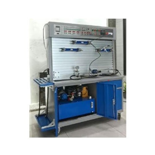
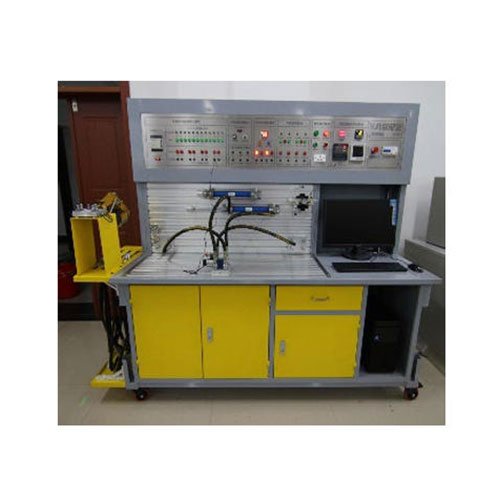
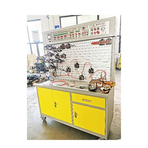
- Hydraulic and pneumatic test bench
- Mechanical teaching equipment
- Robotic automation and mechatronics series
- Welding training equipment

It has a development test analysis system. Through a series of intelligent actions such as flow, pressure, power, speed, torque, displacement, time, temperature, computer human-machine screen — computer intelligent data acquisition, analysis, processing, — automatic production reports, curves, etc., it completes various conventional hydraulic circuits, motors, dynamic and static tests of various valves and pumps. Through experiments, the performance test, intelligent control, remote control of hydraulic systems and the communication technology between hydraulic systems and computers can be mastered and improved.
1. Technical parameters:
1) Input power supply voltage: three-wire five-wire AC380V± 10% 50HZ;
2) Module and component DC voltage: DC24V, 4.5A, with automatic short-circuit protection function;
3) Control voltage: safety control voltage ——DC24V;
4) Operating environment: temperature -10℃~+40℃ relative humidity <85% (25℃) altitude <4000m (dust and moisture proof);
5) Product size: length × width × height = 1600mm*670mm*1820mm;
6) Rated pressure: <=6.3Mpa;
7) Net weight: about 295kg;
8) Hydraulic pump group: equipped with variable vane pump and imported drive motor, oil tank nominal capacity 60L; pump group power 1.5KW, rated pressure 6.3 Mpar, flow rate is 12L/min at speed 1450r/min, nominal displacement 6.67mL/r, volumetric efficiency 90%;
9) Acquisition system: 32-bit channel 12-bit precision PCI data acquisition card, equipped with more than 10 channels of data acquisition software, the parameters of each channel project of the software can be set by itself, and data acquisition and analog output control can be performed; the software has real-time curve and historical curve functions, data report functions, and can collect the collected data in the database, and can call out various data to draw X/Y relationship curves as needed;
2. Main features:
1. Experimental bench: all-steel frame, the main material is 2.0mm thick steel plate, the pump group is closed and hidden design, the experimental bench has drawers, storage cabinets and placement brackets, and the experimental platform is designed with an oil return plate; equipped with universal wheels with self-locking structure, which is convenient for the movement and positioning of the equipment.
2. Connection method and sealing material: The hydraulic connection method adopts a locking quick-change joint, and the seals are all imported high-sealing products, and there is no oil leakage during use.
3. Electrical components: The power supply brand is Taiwan Mean Well, the electrical switch brand is HGG Haige Electric, the relay group brand is Japan Omron Omron, and the AC contactor brand is France Schneider SE. It is also equipped with relay groups, solenoid valve electronic control units, electrical button modules and time relay modules. The electrical access ports are all attached to the electrical control panel of the experimental table. The experimental wires can be easily plugged and unplugged during the experiment; 4. Safety performance: The equipment has electrical grounding, leakage protection (automatic power off when the leakage current exceeds 30mA), phase loss protection, and DC overload protection. The control circuits are all 24V DC safety voltage, and the electrical wires are safe high-insulation experimental wires. 5. Multiple control methods: PLC control, relay control, manual control, software control and other control methods. 6. Software: The equipment is equipped with 3 sets of software, namely: 1 set of data acquisition system software, 1 set of hydraulic simulation teaching software, and 1 set of configuration hydraulic circuit communication control software;
Germany (Festo) FESTO hydraulic simulation software:
Using FluidSIM hydraulic (pneumatic) simulation design software, you can not only demonstrate the structure of various valves, but also design circuits, adjust parameters and simulate actions. Before students actually connect the experimental circuit, they can use this software to repeatedly modify the experimental plan on the computer until the simulation runs successfully. Then use the hydraulic experimental device to actually connect the designed circuit. With the previous simulation system practice foundation, the actual connection is generally smoother. Thereby improving the experimental efficiency.
1. There is a library of hydraulic and electrical standard components, and the technical parameters of related components can be set in the circuit. Can learn hydraulic knowledge and design, test and simulate circuits;
2. Can design and draw circuit diagrams that meet industrial standards, including: hydraulic circuit diagrams, electrical control circuit diagrams, and hydraulic-electric control circuits;
3. The software can determine whether the circuit design is correct and give prompts;
4. The software can reflect the hydraulic platform oil circuit pressure at the time, and the flow is convenient for principle calculation, and free upgrades are provided.
III. Experimental projects:
1. Standard series hydraulic component working principle recognition experiment
2. Hydraulic component performance test experiment;
3. Liquid resistance characteristic performance test experiment;
4. Hydraulic circuit configuration screen demonstration and control experiment;
Hydraulic typical circuit demonstration and control simulation control, can vividly show the flow direction of hydraulic oil, the working state of the internal valve core of various hydraulic valves, the working process of the cylinder and the working principle of the gear pump; can realize direct connection with hardware, and can feedback hardware information to the software to realize automatic synchronization of software and hardware.
(1) Throttle valve switching circuit; (2) Synchronous circuit controlled by throttle valve;
(3) Oil inlet throttling speed control circuit; (4) Two-stage pressure regulating circuit;
(5) Bypass throttling speed control circuit; (6) Three-position four-way reversing circuit;
(7) Sequential circuit controlled by sequence valve; (8) Sequential circuit controlled by pressure relay;
(9) Pressure regulating circuit for changing the pressure of overflow valve spring; (10) Sequential circuit controlled by proximity switch;
(11) Differential circuit; (12) Two-position four-way reversing circuit;
(13) Pressure relief circuit of electromagnetic reversing valve; (14) Pressure stabilizing circuit for isolating pressure fluctuation;
(15) Oil return throttling speed control circuit; (16) Two-way synchronous circuit controlled by throttle valve;
(17) Fast and slow speed switching circuit; (18) Balance circuit;
(19) Hydraulic control check valve locking circuit; (20) Hydraulic control check valve pressure maintaining circuit;
5. Basic hydraulic circuit experiment
(1) Pressure control circuit experiment;
A. Pressure limiting circuit:
a. Pressure setting circuit;
b. Single-stage remote pressure regulating circuit of overflow valve;
c. Multi-stage overflow valve pressure regulating circuit;
d. Overflow valve limiting low pressure circuit (balance circuit).
B. Pressure changing circuit:
a. Primary pressure reducing circuit;
b. Secondary pressure circuit; Multi-way pressure reducing circuit.
C. Unloading circuit:
a. Unloading circuit of reversing valve;
b. Unloading circuit of solenoid reversing valve;
c. Unloading circuit of two-position two-way valve;
d. Unloading circuit of overflow valve.
D. Pressure stabilizing circuit:
a. Hydraulic control check valve pressure maintaining circuit.
E. Pressure relief circuit:
a. Throttle valve pressure relief circuit;
b. Relief valve pressure relief circuit;
c. Sequence valve pressure relief circuit.
F. Pressure reducing circuit
a. Pressure reducing circuit of pressure reducing valve
(2) Speed control circuit experiment;
A. Speed regulating circuit:
a. Oil inlet throttling speed regulating circuit (constant pressure throttling speed regulating circuit, variable pressure throttling speed regulating circuit);
b. Oil return throttling speed regulating circuit;
c. Speed switching circuit with flow valve short circuit;
d. Speed regulating valve control speed regulating circuit I (oil inlet: speed regulating valve constant pressure throttling speed regulating, speed regulating valve variable pressure throttling speed regulating);
e. Speed regulating valve control speed regulating circuit II (oil return: bypass speed regulating);
f. Differential connection speed increasing circuit;
g. Speed reducing circuit of solenoid valve and speed regulating valve;
h. Secondary feed circuit of throttle valve in series/parallel connection;
i. Secondary feed circuit of speed regulating valve in series/parallel connection;
j. Speed switching circuit of speed regulating valve in series connection;
k. Speed switching circuit of speed regulating valve in parallel connection;
l. Differential full pressure switching circuit; m, differential circuit controlled by two-position three-way;
n, differential circuit controlled by three-position four-way; o, secondary feed circuit;
p, tertiary feed circuit; q, differential working switching circuit;
r, volume speed control circuit composed of variable pump and hydraulic cylinder; s, volume speed control circuit composed of variable pump and throttle valve;
t, volume speed control circuit composed of variable pump and speed control valve.
B, synchronous circuit:
a, synchronous circuit controlled by throttle valve; b, synchronous circuit controlled by speed control valve;
c, dual-cylinder synchronous circuit; d, multi-circuit cylinder automatic control circuit.
(3) Direction control circuit experiment;
A. Reversing circuit:
a. Reversing circuit controlled by reversing valve;
b. Sequential action circuit of travel valve;
c. Sequential action circuit of sequence valve;
d. Balance circuit of sequence valve;
e. Sequential action circuit controlled by electrical travel switch;
f. Sequential action circuit controlled by pressure relay;
g. Sequential action circuit controlled by check valve.
B. Locking circuit:
a. Locking circuit with reversing valve;
b. Locking circuit of hydraulically controlled check valve;
c. Locking circuit of check valve;
d. Locking circuit with “O” type and “H” type functional reversing valve
C. Sequential circuit:
a. Sequential action circuit with sequence valve;
b. Sequential action circuit with electrical travel switch;
c. Sequential action circuit with pressure relay.
D. Balancing circuit:
a. Balancing circuit using sequence valve; b. Balancing circuit using hydraulically controlled one-way valve;
c. Balancing circuit using one-way speed regulating valve; d. Balancing circuit using one-way throttle valve.
E. Buffering circuit:
a. Balancing circuit using overflow valve; b. Buffering circuit using speed regulating valve;
c. Buffering circuit using throttle valve.
(4) Other comprehensive assembly and expansibility circuit experiments.
6. Intelligent data acquisition system experiment: reisition, analysis, processing, instant display, automatic generation and printing of experimental curves for pressure, flow, power speed, temperature and other data.
7. Programmable logic controller (PLC) electrical control experiment, electromechanical and hydraulic integrated control experiment.
(1) Learning of PLC instruction programming and ladder diagram programming;
(2) Learning and using PLC programming software;
(3) Communication between PLC and computer, online debugging and monitoring;
(4) Application of PLC in hydraulic transmission control and optimization of control scheme.