- Automobile training equipment series
- Electrical and electronic teaching equipment
- Elevator training series
- Fitter training equipment
- Fluid mechanics experimental equipment
- Hydraulic and pneumatic test bench
- Mechanical teaching equipment
- Robotic automation and mechatronics series
- Welding training equipment

I. Overview
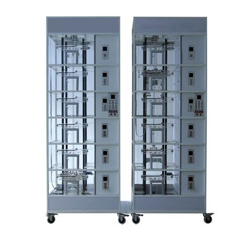
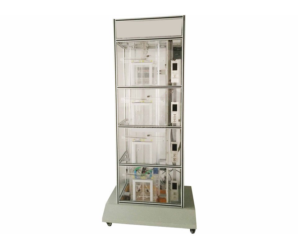
The passenger and cargo dual-purpose transparent simulation teaching elevator model is an experimental demonstration teaching equipment developed for the development of elevator and industrial automation courses in colleges, technical schools, vocational schools, labor employment training centers, and special equipment testing centers for training elevator operation certificates, elevator maintenance and property management, and other related elevator and industrial automation courses. Its appearance uses transparent imported organic glass materials, so that students can better understand the use of elevators, structural principles, operating principles, and control methods, and cultivate more elevator professionals to meet the development needs of elevator and automation majors. After many on-site inspections, our company has cooperated with elevator manufacturers and elevator experts to develop simulation teaching models for passenger elevators and freight elevators. The passenger elevator is 1:1 traction type, the door opening method is middle split, and the freight elevator is 2:1 traction type, and the door opening method is double fold left door, which allows students to understand and intuitively see the operating status of each operating mechanism.
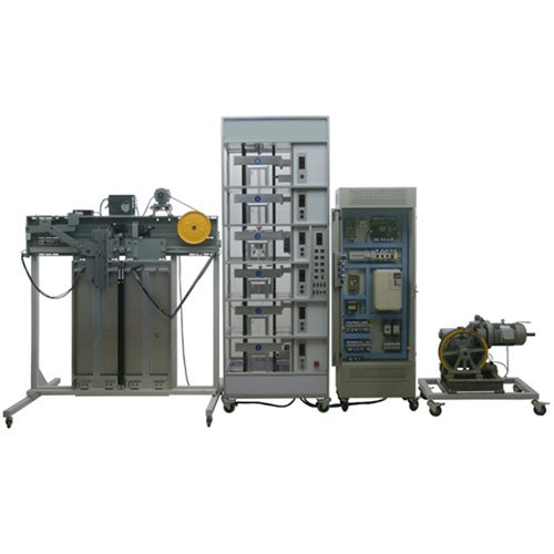
The elevator’s electrical control system utilizes an imported programmable controller (PLC, Mitsubishi, Japan) for intelligent control and a variable frequency drive (VVVF, Yaskawa, Japan) for voltage, speed, and frequency regulation. Its component structure, operating principles, and functions are identical to those of an actual elevator, and it also features a safety clamp speed limiter and overspeed safety protection system. 1. This elevator utilizes an industrial aluminum profile frame, with the base integrated into the elevator shaft, resulting in an elegant, durable, and sturdy structure.
2. The base is crafted from 1.2mm cold-rolled steel plate and shot-peened. It features custom-made universal casters for easy movement.
3. All key components of the elevator are crafted from imported transparent plexiglass, fully simulating all the functions of a real elevator.
4. The elevator features voice announcements, accurately announcing the elevator’s current floor, upper and lower positions, and overload status.
5. The elevator’s electrical control system is controlled by a separate electrical control cabinet.
II. Basic Elevator Structure
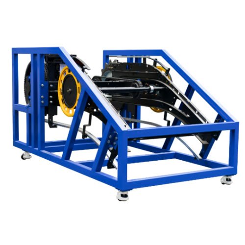
1. Machine Room:
Includes the traction machine, brake, speed limiter, traction sheave, guide pulley or rewinding pulley, manual winch pulley, control cabinet, power switch, car lighting switch, and shaft lighting switch. 2. Approach Section:
Car, car guide rails, counterweight guide rails, counterweight frame, buffers, limit switches, limit switches, control cables, support cables, and speed governor wire tensioner.
3. Car Section:
Car, safety gear, guide shoes, automatic door opener/closer, leveling device, control panel, car command buttons, floor indicator lights, car lighting, car inspection box, and car door.
4. Landing Door Components:
Hall door, call button box, floor indicator, door mechanical lock, and electrical interlocking device. 5. Power Distribution Cabinet Control Section
The independent power distribution cabinet (specifications: 800 × 450 × 1500 mm) contains the main power supply, control power supply, PLC programmable controller, frequency converter, terminal block, and other equipment.
III. Basic Elevator Functions
A. Overspeed Safety Protection System
When an elevator accident occurs, such as the car overspeeding or descending at high speed (e.g., wire rope breakage, disengagement of the car top pulley, traction machine worm gear failure, excessive motor speed), the speed limiter activates the emergency brake. Through the safety cable and linkage mechanism, the safety clamp activates, locking the car on the guide rails and preventing it from falling.
B. Spring Buffers for Car and Counterweight
Buffers are safety devices for elevator extreme positions. When an elevator malfunction causes the car or counterweight to bottom out or top out (resulting in ineffective limit switch protection), the car or counterweight impacts the spring buffer, which absorbs the elevator’s energy, safely slowing the car or counterweight to a stop. C. Upper and Lower Limit Switches:
These switches are installed at the upper and lower ends of the elevator shaft, within the upper and lower limit switches. Their purpose is to protect the elevator car from exceeding these limits. If the upper or lower limit is exceeded, the motor automatically stops and ceases operation. Unlike the upper and lower limit switches, these switches do not lose power.
D. Landing Door Automatic Closing Device:
The elevator landing doors are opened and closed by door blades installed on the car doors. Each landing door is equipped with a door lock. When the landing door is closed, the mechanical lock hook of the door lock engages, allowing the elevator to start.
E. Landing Door Interlock Switch:
When all landing doors are closed, the elevator can ascend or descend. If even one landing door is open, the elevator cannot operate.
F. Terminal Limit Switch Safety Protection System: Terminal limit switches are installed at the top and bottom floors of the elevator shaft. If the elevator loses control due to a malfunction and the car hits the top or bottom, the terminal limit switches activate, generating an alarm signal and disconnecting the control circuit, causing the car to stop. Passenger and freight transparent simulation teaching elevator model
IV. Main Technical Parameters
1. Input voltage: AC 380 ± 7% 50Hz
2. Dimensions: Width 1500mm × Depth 90mm × Height 2200mm
3. Landing configuration: Passenger elevator (four floors, four landings, four doors); Freight elevator (four floors, four landings, four doors).
4. Control method: Programmable Logic Controller (PLC) with voltage, speed, and frequency (VVVF) collective control.
5. Structure: Four-story station
6. Programmable Logic Controller (PLC): Model: Mitsubishi FXzn-64MR
Input Voltage: AC 220V 50Hz
Input and Output Points: 64 (32 inputs, 32 outputs)
Output Method: Relay Output
7. Variable Frequency Drive: Model: TE380 3007
Input Voltage: AC 220V 60Hz
Rated Current: 2.5A
Power: 1.2kW
8. Traction Motor: Speed Ratio: 30:1
Module: 1.5 (Worm Gear Reducer)
9. Traction Motor: Model: JW5622
Voltage: AC 220V 50Hz
Power: 180W
Speed: 2800rpm
V. Training Items
1. Car Start/Stop, Inching Control Training
2. Car Leveling Control Training
3. Training on opening and controlling elevator doors
4. Training on terminal limit protection devices
5. Training on speed limit protection devices
6. Training on voice announcement functions
7. Training on signal indication systems
8. Training on elevator lighting control
9. Training on elevator control systems
10. Training on elevator control programming
11. Training on elevator program operation and debugging
12. Training and assessment on over 20 common elevator faults